Sharp CD-DP2400H (serv.man19) Service Manual ▷ View online
– 3 –
CD-DP2400H
FOR A COMPLETE DESCRIPTION OF THE OPERATION OF THIS UNIT, PLEASE REFER TO
THE OPERATION MANUAL.
THE OPERATION MANUAL.
Specifications for this model are subject to change without prior
notice
notice
SPECIFICATIONS
■
General
■
Amplifier
■
CD player
■
Tuner
■
Cassette deck
■
Front speaker
■
Centre speaker
■
Surround speaker
Power source
AC 230 V, 50 Hz
Power consumption
108 W
Dimensions
Width: 270 mm (10-5/8")
Height: 330 mm (13")
Depth: 332 mm (13-1/16")
Height: 330 mm (13")
Depth: 332 mm (13-1/16")
Weight
8.0 kg (17.6 lbs.)
Output power
Front speakers:
RMS: 60 W (30 W + 30 W) (10 % T.H.D.)
RMS: 46 W (23 W + 23 W) (0.9 % T.H.D.)
RMS: 46 W (23 W + 23 W) (0.9 % T.H.D.)
Centre speaker:
RMS: 20 W (10 % T.H.D.)
RMS: 16 W (0.9 % T.H.D.)
RMS: 16 W (0.9 % T.H.D.)
Surround speakers:
RMS: 20 W (10 W + 10 W) (10 % T.H.D.)
RMS: 16 W (8 W + 8 W) (0.9 % T.H.D.)
RMS: 16 W (8 W + 8 W) (0.9 % T.H.D.)
Output terminals
Front speakers: 6 ohms
Centre speaker: 6 ohms
Surround speakers: 12 ohms
Surround speakers: 12 ohms
Headphones: 16 - 50 ohms (recommended: 32 ohms)
Input terminals
Video/Auxiliary (audio signal): 500 mV/47 kohms
Type
3-disc multi-play compact disc player
Signal readout
Non-contact, 3-beam semiconductor laser pickup
D/A converter
1-bit D/A converter
Frequency response
20 - 20,000 Hz
Dynamic range
90 dB (1 kHz)
Frequency range
FM: 87.5 - 108 MHz
AM: 522 - 1,620 kHz
Frequency response
50 - 14,000 Hz (Normal tape)
Signal/noise ratio
55 dB (TAPE 1, playback)
50 dB (TAPE 2, recording/playback)
50 dB (TAPE 2, recording/playback)
Wow and flutter
0.3 % (WRMS)
Type
2-way type speaker system
5 cm (2") Tweeter
13 cm (5-1/4") Woofer
Maximum input power 60 W
Rated input power
30 W
Impedance
6 ohms
Dimensions
Width: 220 mm (8-11/16")
Height: 330 mm (13")
Depth: 217 mm (8-9/16")
Height: 330 mm (13")
Depth: 217 mm (8-9/16")
Weight
3.0 kg (6.6 lbs.)/each
Type
10 cm (4") full-range speaker
Maximum input power 40 W
Rated input power
20 W
Impedance
6 ohms
Dimensions
Width: 260 mm (10-1/4")
Height: 140 mm (5-1/2")
Depth: 155 mm (6-1/8")
Height: 140 mm (5-1/2")
Depth: 155 mm (6-1/8")
Weight
0.9 kg (2.0 lbs.)
Type
10 cm (4") full-range speaker
Maximum input power 20 W
Rated input power
10 W
Impedance
12 ohms
Dimensions
Width: 200 mm (7-7/8")
Height: 93 mm (2-11/16")
Depth: 170 mm (6-3/4")
Height: 93 mm (2-11/16")
Depth: 170 mm (6-3/4")
Weight
0.5 kg (1.1 lbs.)/each
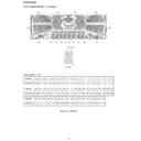
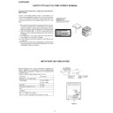
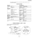
If any one of the bands shoen in Fig.3 is removed for some
reason,be sure replace it to the original position and same
appearance as before.
reason,be sure replace it to the original position and same
appearance as before.
WIRING OF PRIMARILY SUPPLY LEADS
AC Power
Supply Cord
Supply Cord
Power
Transformer
Transformer
Brown
Blue
Nylon Band 80mm
92LNBAND1318A
92LNBAND1318A
Figure 3
CD-DP2400H
– 4 –
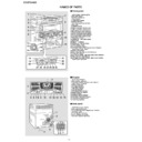
NAMES OF PARTS
■
Front panel
1. Disc Number Select Buttons
2. Disc Skip Button
3. On/Stand-by Button
4. Clock Button
5. Timer/Sleep Button
6. Dimmer Button
7. Disc Tray Open/Close Button
8. Disc Tray
9. Volume Control
2. Disc Skip Button
3. On/Stand-by Button
4. Clock Button
5. Timer/Sleep Button
6. Dimmer Button
7. Disc Tray Open/Close Button
8. Disc Tray
9. Volume Control
10.Tape 2 Cassette Compartment
11.Tape 1 Cassette Compartment
12.Normal Button (with Indicator)
13.Bypass Button (with Indicator)
14.Extra Bass/Demo Mode Button
15.Phantom Button (with Indicator)
16.Equalizer Mode Select Button
17.Headphone Socket
18.Tuning and Time Down Button
19.CD Button
20.Tape (1 2) Button
21.Tuning and Time Up Button
22.Tuner (Band) Button
23.Video/Auxiliary Button
24.CD Track Down or Fast Reverse, Tape 2 Rewind,
Tuner Preset Down Button
25.Memory/Set Button
26.CD or Tape Stop Button (with Indicator)
27.Timer Set Indicator
28.CD Play or Repeat, Tape Play Button (with Indicator)
29.Tape 2 Record Pause Button
30.CD Track Up or Fast Forward, Tape 2 Fast Forward,
26.CD or Tape Stop Button (with Indicator)
27.Timer Set Indicator
28.CD Play or Repeat, Tape Play Button (with Indicator)
29.Tape 2 Record Pause Button
30.CD Track Up or Fast Forward, Tape 2 Fast Forward,
Tuner Preset Up Button
1
7
8
9
10
11
2
3
4
5
6
18
21
22
23
23
19
20
20
24 25 26 27 28 29 30
12
15
16
17
13
14
■
Display
1. Extra Bass Indicator
2. Disc Number Indicators
3. Spectrum Analyser/Volume Level Indicator
4. Tape 2 Record Indicator
5. Memory Indicator
6. CD Pause Indicator
7. Tape Play Indicator
8. CD Play Indicator
9. CD Repeat Play Indicator
2. Disc Number Indicators
3. Spectrum Analyser/Volume Level Indicator
4. Tape 2 Record Indicator
5. Memory Indicator
6. CD Pause Indicator
7. Tape Play Indicator
8. CD Play Indicator
9. CD Repeat Play Indicator
10.Music Schedule Indicator
11.Sleep Indicator
12.FM Stereo Mode Indicator
13.FM Stereo Receiving Indicator
14.Timer Recording Indicator
15.Timer Play Indicator
11.Sleep Indicator
12.FM Stereo Mode Indicator
13.FM Stereo Receiving Indicator
14.Timer Recording Indicator
15.Timer Play Indicator
■
Rear panel
1. FM 75 Ohms Aerial Socket
2. AM Loop Aerial Socket
3. Video/Auxiliary (Audio Signal) Input Sockets
4. AC Power Lead
5. Front Speaker Terminals
6. Centre Speaker Terminals
7. Surround Speaker Terminals
2. AM Loop Aerial Socket
3. Video/Auxiliary (Audio Signal) Input Sockets
4. AC Power Lead
5. Front Speaker Terminals
6. Centre Speaker Terminals
7. Surround Speaker Terminals
2
1
3
4
15
6
5
7 8 9
10
11 12 13 14
4
3
3
1
2
5 6 7
– 5 –
CD-DP2400H
■
Front speaker
1. Tweeter
2. Woofer
3. Bass Reflex Duct
4. Speaker Wire
2. Woofer
3. Bass Reflex Duct
4. Speaker Wire
■
Centre speaker
1. Full-Range Speaker
2. Speaker Wire
2. Speaker Wire
■
Surround speaker
1. Full-Range Speaker
2. Speaker Wire
2. Speaker Wire
Notes:
●
The speaker grilles on the centre and surround speakers are not removable.
●
When the surround speakers are not installed on the wall, the speaker badge will
be upside down. In this case, you can adjust the badge to face the proper direction
by turning it by hand.
be upside down. In this case, you can adjust the badge to face the proper direction
by turning it by hand.
3
4
1
2
3
1
2
1
2
Front speaker grilles are removable:
Make sure nothing comes into contact with the speaker
diaphragms when you remove the speaker grilles.
diaphragms when you remove the speaker grilles.
Badge
■
Remote control
1. Remote Control Transmitter
2. Surround Level Up and Down Buttons
3. Centre Level Up and Down Buttons
4. Dolby Pro Logic Button
5. Balance Control Up and Down Buttons
6. Test Tone Button
7. CD Pause Button
8. CD Memory Button
9. CD Track Down or Fast Reverse Button
2. Surround Level Up and Down Buttons
3. Centre Level Up and Down Buttons
4. Dolby Pro Logic Button
5. Balance Control Up and Down Buttons
6. Test Tone Button
7. CD Pause Button
8. CD Memory Button
9. CD Track Down or Fast Reverse Button
10.CD Clear Button
11.Tape 1 Play Button
12.Tape 1/Tape 2 Stop Button
13.Equalizer Mode Select Button
14.Tape 2 Record Pause Button
15.CD Button
16.On/Stand-by Button
17.Tuner (Band) Button
18.Tuner Preset Up and Down Buttons
19.CD Stop Button
20.CD Play or Repeat Button
21.CD Track Up or Fast Forward Button
22.CD Random Button
23.Tape 2 Play Button
24.Disc Skip Button
25.Tape 2 Fast Forward Button
26.Tape 2 Rewind Button
27.Video/Auxiliary Button
28.Tape (1 2) Button
29.Volume Up and Down Buttons
30.Extra Bass Button
1
2
3
4
5
6
7
8
9
8
9
10
11
12
13
12
13
14
15
16
17
19
18
20
21
22
23
24
25
24
25
26
27
28
29
30
Buttons with " " mark in the illustration can be operated on the remote control
only.
Other buttons can be operated both on the main unit and the remote control.
CD-DP2400H
– 6 –
OPERATION MANUAL
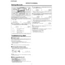
In this example, the clock is set for the 24-hour (0:00) display.
Note:
The "CLOCK" or time will flash at the push of the CLOCK button when the AC power
supply is restored after a power failure or unplugging the unit.
Readjust the clock as follows.
supply is restored after a power failure or unplugging the unit.
Readjust the clock as follows.
To readjust the clock:
Perform "Setting the clock" from the beginning. If the time display is flashing, step 3
(for selecting the 24-hour or 12-hour display) will be skipped.
(for selecting the 24-hour or 12-hour display) will be skipped.
To change the 24-hour or 12-hour display:
1
Press the ON/STAND-BY button to turn the power on.
2
Press the CLOCK button and within 5 seconds, press the MEMO-
RY/SET button.
RY/SET button.
3
Press the TUNING/TIME ( or ) button to select 24-hour or 12-
hour display and then press the MEMORY/SET button.
hour display and then press the MEMORY/SET button.
"0:00"
The 24-hour display will appear.
(0:00
-
23:59)
"AM 12:00"
The 12-hour display will appear.
(AM 12:00 - PM 11:59)
"AM 0:00"
The 12-hour display will appear.
(AM 0:00 - PM 11:59)
Note that this can only be set when the unit is first installed or it has been reset.
4
Press the TUNING/TIME ( or ) button to adjust the hour and then
press the MEMORY/SET button.
press the MEMORY/SET button.
●
Press the TUNING/TIME ( or ) button once to advance the time by 1 hour.
Hold it down to advance continuously.
Hold it down to advance continuously.
●
When the 12-hour display is selected, "AM" will change automatically to "PM".
5
Press the TUNING/TIME ( or ) button to adjust the minutes and
then press the MEMORY/SET button.
then press the MEMORY/SET button.
●
Press the TUNING/TIME ( or ) button once to advance the time by 1
minute. Hold it down to change the time in 5-minute intervals.
minute. Hold it down to change the time in 5-minute intervals.
●
The hour will not advance even if minutes advance from "59" to "00".
●
The clock begins counting from "0" seconds. (Seconds are not displayed.)
The time display will disappear after a few seconds.
The time display will disappear after a few seconds.
To confirm the time display:
Press the CLOCK button.
The time display will appear for about 5 seconds.
The time display will appear for about 5 seconds.
1
Clear all the programmed contents.
2
Perform "Setting the clock" from the beginning.
Setting the clock
Troubleshooting chart
■
If trouble occurs
When this product is subjected to strong external interference (mechanical shock,
excessive static electricity, abnormal supply voltage due to lightning, etc.) or if it is
operated incorrectly, it may malfunction.
excessive static electricity, abnormal supply voltage due to lightning, etc.) or if it is
operated incorrectly, it may malfunction.
If such a problem occurs, do the following:
1
1
Set the unit to the stand-by mode and turn the power on again.
2
If the unit is not restored in the previous operation, unplug and plug in the unit,
and then turn the power on.
and then turn the power on.
Note:
If neither operation above restores the unit, clear all the memory by resetting it.
■
Clearing all the memory (reset)
1
Press the ON/STAND-BY button to enter the power stand-by mode.
2
Whilst pressing down the / button and the X-BASS/DEMO button, press the
ON/STAND-BY button until "CLEAR AL" appears.
ON/STAND-BY button until "CLEAR AL" appears.
Caution:
This operation will erase all data stored in memory including clock, timer settings,
tuner preset, and CD programme.
tuner preset, and CD programme.
■
Before transporting the unit
1
Press the ON/STAND-BY button to turn the power on.
2
Press the CD button.
3
Press the OPEN/CLOSE button to open the disc tray.
Remove all CDs inserted in the unit.
Remove all CDs inserted in the unit.
4
Press the OPEN/CLOSE button to close the disc tray.
Make sure that "NO DISC" is displayed.
Make sure that "NO DISC" is displayed.
5
Press the ON/STAND-BY button to enter the stand-by mode, and then unplug
the AC power lead from the wall socket.
the AC power lead from the wall socket.

