Sharp CD-DP2400E (serv.man9) Service Manual ▷ View online
CD-DP2400E
– 12 –
SP out
L-ch
Input signal is output.
(SO901)
R-ch
Input signal is output.
(SO901) SP out C-ch
SP cut, no output
(SO901) SP out S-ch
Almost no output (only omitting component)
SP out
L-ch
Almost no output (only omitting component)
(SO901)
R-ch
Almost no output (only omitting component)
(SO901) SP out C-ch Input signal is output.
(SO901) SP out S-ch
Almost no output (only omitting component)
State of set Dolby Pro Logic
Dolby Pro Logic On mode
Output point
Bypass mode
Normal mode
Phantom mode
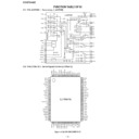
IC501
1 pin L-out
Output enabled state
Output enabled state
Output enabled state
2 pin R-out
Output enabled state
Output enabled state
Output enabled state
IC501
3pin C-out
No output
Output enabled state
No output
IC501
9pin S-out
No output
Output enabled state
Output enabled state
SP OUT
L-ch
Output enabled state
Output enabled state
Output enabled state
(SO901)
R-ch
Output enabled state
Output enabled state
Output enabled state
SP OUT C-ch
No output in MUTE (Q501) state
Output enabled state
No output in MUTE (Q501) state
(SO901)
SP OUT S-ch
No output in MUTE (Q502) state
Output enabled state
Output enabled state
(SO901)
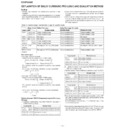
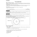
EXPLANATION OF DOLBY SURROUND PRO LOGIC AND EVALUATION METHOD
Test tone output
• Pro Logic ON Normal mode
Press the remote control TEST TONE button.
• Pro Logic ON Normal mode
Press the remote control TEST TONE button.
→
Output of only L-ch
→
Output of only C-ch
↑
↓
Output of only S-ch
←
Output of only R-ch
The test tone (noise) is repeatedly output for output period
(2 sec).
In this case the following indication appears repeatedly.
(2 sec).
In this case the following indication appears repeatedly.
→
TEST
→
L-ch
→
C-ch
↑
↓
S-ch
←
R-ch
• Pro Logic ON Phantom mode
Press the remote control TEST TONE button.
Press the remote control TEST TONE button.
→
Output of only L-ch
→
Output of only R-ch
↑
↓
←
Output of only S-ch
The test tone (noise) is repeatedly output for output period
(2 sec).
(2 sec).
In this case the following indication appears repeatedly.
→
TEST
→
L-ch
→
R-ch
↑
↓
←
S-ch
←
Outline
• Namely, two speakers are connected in parallel to one
amplifier.
• In the Pro Logic BYPASS mode the amplifier for C-ch (center
channel) and the amplifier for S-ch (surround channel) are in
MUTE state. The SP output is cut.
MUTE state. The SP output is cut.
• In the normal mode of Pro Logic ON mode the amplifiers for
C-ch and S-ch are in operative state, so that the SP output
appears.
appears.
• In the Phantom mode of Pro Logic ON mode the amplifier for
C-ch is in MUTE state, so that the SP output is cut. The
amplifier for S-ch (surround) is in operative state, so that the
SP output appears
amplifier for S-ch (surround) is in operative state, so that the
SP output appears
•
State of element output and terminal output in specific mode
Relation between VIDEO IN input and output in Pro Logic
ON state
(1) L-ch/R-ch same phase input into VIDEO IN input jack in
ON state
(1) L-ch/R-ch same phase input into VIDEO IN input jack in
VIDEO Function mode
Output point
Normal mode
Output point
Phantom mode
(2) L-ch/R-ch reverse phase input into VIDEO IN input jack in
VIDEO Function mode
(Reverse phase: Phase difference between L and R is 180
°
)
Output point
Normal mode
SP out
L-ch
Almost no output (only omitting component)
(SO901)
R-ch
Almost no output (only omitting component)
(SO901) SP out C-ch
Almost no output (only omitting component)
(SO901) SP out S-ch
Input signal is output.
Output point
Phantom mode
SP out
L-ch
Almost no output (only omitting component)
(SO901)
R-ch
Almost no output (only omitting component)
(SO901) SP out C-ch
SP cut, no output
(SO901) SP out S-ch
Input signal is output.
• Accordingly, if you want to output signal waveform to C-ch SP
out, give the same phase input into L-ch/R-ch INPUT in the
Pro Logic Normal mode.
Pro Logic Normal mode.
If one of channels receives input, C-ch does not output. Only
L-ch or R-ch outputs.
• If you want to output signal waveform to S-ch SP out, you can
use either Normal mode or Phantom mode. However, 180
°
reverse phase input must be given to L-ch/R-ch INPUT.
– 13 –
CD-DP2400E
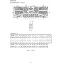
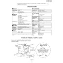
TEST MODE
KEY
TEST MODE
CONTENTS
[ON/STAND-BY] [TUNER] + [X-BASS]
TEST 1
TUNER PRESET MEMORY CLEAR
[ON/STAND-BY] [MEMORY/SET] + [X-BASS]
TEST 2
TUNER PRESET FOR PRODUCTION
[ON/STAND-BY] [>>] + [X-BASS]
TEST 3
KEY AND DISPLAY TEST
[ON/STAND-BY] [CD] + [X-BASS]
TEST 4
CD TEST MODE
[ON/STAND-BY] [TAPE] + [X-BASS]
TEST 5
TAPE TEST MODE
[ON/STAND-BY] [>] + [X-BASS]
TEST 6
ALL CLEAR(RESET)
[ON/STAND-BY] [TUN UP] + [X-BASS]
TEST 7
AUDIO TEST
[ON/STAND-BY] [TUN DOWN] + [X-BASS]
TEST 8
PRODUCTION INITIALIZE FOR CHANGER
During POWER OFF mode,push below each 2 keys [ON/STAND-BY] key.
Then go to each TEST MODE.
Then go to each TEST MODE.
Display

