Sharp CD-CH1000 (serv.man25) Service Manual ▷ View online
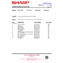
– 17 –
CD-CH1000H/CD-CH1000W
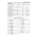
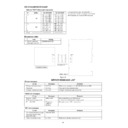
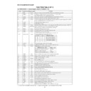
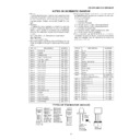
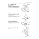
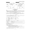
1. Motor assembly (x 2) mounting (screw x 4)
101/129
Fig. 18
2. MT idle gear mounting (screw x 1)
125
Fig. 18
3. MT system gear assembly
123/124/126/127
Fig. 18
4. STB/tray drive system gear and others assembling/ 137/138/145/146 (153)/147/148
Fig. 18
mounting (screw x 3)
5. Tray big gear assembly
131
Fig. 18
Gear positioning
6. T.M SW PWB mounting (screw x 3)
Fig. 19
7. STB holder assembling
103
Fig. 18
8. STB drive gear L/R assembly mounting (screw x 2)
111 (110)/112 (110)
Fig. 18
9. Tray joint gear R/tray drive gear R assembling
134/136
Fig. 19
Gear positioning
10. Tray gear A/B assembling
132/133
Fig. 19
Gear positioning
11. Lift gear B/C assembling
143/144
Fig. 20
Gear positioning
12. MT idler gear F assembling, mode big gear
128/142
Fig. 20
mounting (screw x 1)
13. Change box R mounting (screw x 4)
104
Fig. 20
14. Lift gear A assembling
142
Fig. 20
Gear positioning
15. Change box L assembly mounting (screw x 4)
102/130/135
Fig. 21
16. Lift cam assembling (shaft inserting)
144
Fig. 21
Gear positioning
17. STB holder height adjusting
Fig. 22
Check/adjustment
18. Top plate F/disc OB LEV. mounting (screw x 6)
180
Fig. 22
19. Trays 1 - 6 assembling
191/192/193/194/195/196
Fig. 23
20. Top plate R mounting (screw x 6)
—
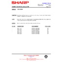
Applied part No.
Work content
Assembly fig. No.
Remarks
CD CHANGER MECHANISM MAIN BASE PARTS ASSEMBLING/ADJUSTING
PROCEDURE
PROCEDURE
101
MAIN BASE
102
CHANGE BOX L
103
STB HOLDER
104
CHANGE BOX R
110
STB DRIVE GEAR A
111
STB DRIVE GEAR L
112
STB DRIVE GEAR R
120
STABILIZER FH
123
MT IDLER GEAR A
124
MT IDLER GEAR B
125
MT IDLER GEAR C
126
MT IDLER GEAR D
127
MT IDLER GEAR E
128
MT IDLER GEAR F
129
MOTOR GEAR
130
TRAY DRIVE GEAR F
131
TRAY BIG GEAR
132
TRAY GEAR A
133
TRAY GEAR B
134
TRAY DRIVE GEAR R
135
TRAY JOINT GEAR F
136
TRAY JOINT GEAR R
137
TRAY GEAR C
138
TRAY IDLER GEAR
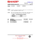
Part name
No.
140
LIFT CAM
141
MODE BIG GEAR
142
LIFT GEAR A
143
LIFT GEAR B
144
LIFT GEAR C
145
STB GEAR A
146
STB GEAR B
147
STB GEAR C
148
STB GEAR D
150
LIFT LEVER
151
TRAY LOCK LEVER
152
DISC OB LEVER
153
STB GEAR ANG.
180
TOP PLATE F
181
TOP PLATE R
191
TRAY 1
192
TRAY 2
193
TRAY 3
194
TRAY 4
195
TRAY 5
196
TRAY 6
Part name
No.
CD CHANGER MECHANISM PARTS LIST
CD-CH1000H/CD-CH1000W
– 18 –
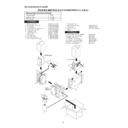
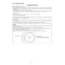
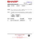
Figure 18
131
TRAY BIG GEAR
TRAY BIG GEAR
131
TRAY BIG GEAR
TRAY BIG GEAR
137
TRAY GEAR C
TRAY GEAR C
138
TRAY IDLER GEAR
TRAY IDLER GEAR
137
TRAY GEAR C
TRAY GEAR C
138
TRAY IDLER GEAR
TRAY IDLER GEAR
147
STB GEAR C
147
STB GEAR C
146
STB GEAR B
146
STB GEAR B
STB GEAR B
110
STB DRIVE GEAR A
129
101
MAIN BASE
MAIN BASE
129
123
123
124
125
126
127
Mark position
103
STB HOLDER
STB HOLDER
148
STB GEAR D
STB GEAR D
112
STB DRIVE GEAR R
(ASS'Y)
111
STB DRIVE GEAR L
(ASS'Y)
111(/112) (110)
STB DRIVE GEAR L(/R)
(ASS'Y)
STB DRIVE GEAR L(/R)
(ASS'Y)
110
STB DRIVE GEAR A
145
STB GEAR A
145
STB GEAR A
153
STB GEAR ANG.
153
STB GEAR ANG.
After assembling TRAY BIG GEAR, turn it in the arrow direction.
TRAY BIG GEAR ASSEMBLING POSITION
– 19 –
CD-CH1000H/CD-CH1000W
Figure 19
131
M T SW PWB
133
TRAY
GEAR B
TRAY
GEAR B
132
TRAY GEAR A
TRAY GEAR A
133
TRAY GEAR B
137
132
TRAY GEAR A
TRAY GEAR A
138
134
TRAY DRIVE GEAR R
TRAY DRIVE GEAR R
136
TRAY JOINT GEAR R
TRAY JOINT GEAR R
147
146
134
TRAY DRIVE GEAR R
TRAY DRIVE GEAR R
136
TRAY JOINT GEAR R
TRAY JOINT GEAR R
110
129
129
123
123
124
125
126
127
Mark position
111
145
TRAY BIG GEAR SET POSITION
133
132
Direct the recess part
(trapezoidal side) of the axis
135 in this direction.
(trapezoidal side) of the axis
135 in this direction.
* This position becomes the
reference (stock) position
of the tray.
reference (stock) position
of the tray.
These holes must align.
It must not rotate in contact
with the peripheral (hatched)
part of 131.
with the peripheral (hatched)
part of 131.
These holes must align.
After assembling 132,
assemble 133.
assemble 133.
*1: To position the axis part of 136, engage it with 138.
*2: When it is aligned as described in *1, the hatched part
(low gear-height part of gear) will be positioned in this position.
Note: After positioning the tray big gear in the set position, engage these gears.
*2: When it is aligned as described in *1, the hatched part
(low gear-height part of gear) will be positioned in this position.
Note: After positioning the tray big gear in the set position, engage these gears.
*1
*2
Scale: 2 magnifications
Scale: 2 magnifications
CD-CH1000H/CD-CH1000W
– 20 –
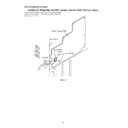
Figure 20
143
LIFT GEAR B
141
MODE BIG GEAR
MODE BIG GEAR
133
132
104
CHANGE BOX R
CHANGE BOX R
147
146
128
MT IDLER GEAR F
110
Mark position
111
145
142
LIFT GEAR A
153
137
138
144
LIFT GEAR C
LIFT GEAR C
134
136
(A)
(B)
144
LIFT GEAR C
LIFT GEAR C
143
LIFT GEAR B
142
LIFT GEAR A
LIFT GEAR A
141
MODE BIG GEAR
MODE BIG GEAR
Note
(Assemble the mode big gear in this position.)
To assemble the mode
big gear, incline it,
bring it into contact with
the circumference and
put the center hole into
position since the
hatched part of the main
base is overlapped with
the circumference.
big gear, incline it,
bring it into contact with
the circumference and
put the center hole into
position since the
hatched part of the main
base is overlapped with
the circumference.
Direct the short tooth
toward the center.
toward the center.
MODE BIG GEAR
LIFT GEAR A/B/C
ASSEMBLING POSITION
LIFT GEAR A/B/C
ASSEMBLING POSITION
Scale: 2 magnifications
Scale: 2 magnifications
<Assembling method of lift gear>
After setting up the mode big gear in the
shown position, engage it with the STB gear A
(gear on the lower side) at the position (A),
and assemble them, turning it in the arrow direction
into the position (B). (The short tooth directs toward the
center of the mode big gear.)
shown position, engage it with the STB gear A
(gear on the lower side) at the position (A),
and assemble them, turning it in the arrow direction
into the position (B). (The short tooth directs toward the
center of the mode big gear.)
,,,,,,,,,,,,,,,,
,,,,,,,,,,,,,,,,
,,,,,,,,,,,,,,,,
,,,,,,,,,,,,,,,,
,,,,,,,,,,,,,,,,
,,,,,,,,,,,,,,,,
,,,,,,,,,,,,,,,,
,,,,,,,,,,,,,,,,
,,,,,,,,,,,,,,,,
,,,,,,,,,,,,,,,,
,,,,,,,,,,,,,,,,
,,,,,,,,,,,,,,,,
,,,,,,,,,,,,,,,,
,,,,,,,,,,,,,,,,
,,,,,,,,,,,,,,,,
,,,,,,,,,,,,,,,,
,,,,,,,,,,,,,,,,
,,,,,,,,,,,,,,,,
,,,,,,,,,,,,,,,,
,,,,,,,,,,,,,,,,
,,,,,,,,,,,,,,,,
,,,,,,,,,,,,,,,,
,,,,,,,,,,,,,,,,
,,,,,,,,,,,,,,,,
,,,,,,,,,,,,,,,,
,,,,,,,,,,,,,,,,
Display

