Sharp CD-C3H (serv.man13) Service Manual ▷ View online
CD-C3H/CP-C3H
– 60 –
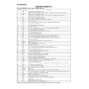
52
S20/PC4
S23
Output
Display tube segment drive
53
S21/PC5
S22
Output
Display tube segment drive
54
S22/PC6
S21
Output
Display tube segment drive
55
S23/PC7
S20
Output
Display tube segment drive
56
S24/PD0
S19
Output
Display tube segment drive
57
S25/PD1
S18
Output
Display tube segment drive
58
S26/PD2
S17
Output
Display tube segment drive
59
S27/PD3
S16
Output
Display tube segment drive
60
S28/PD4
S15
Output
Display tube segment drive
61
S29/PD5
S14
Output
Display tube segment drive
62
S30/PD6
S13
Output
Display tube segment drive
63
S31/PD7
S12
Output
Display tube segment drive
64
S32/PE0
S11
Output
Display tube segment drive
65
S33/PE1
S10
Output
Display tube segment drive
66
S34/PE2
S9
Output
Display tube segment drive
67
S35/PE3
S8
Output
Display tube segment drive
68
S36/PE4
S7
Output
Display tube segment drive
69
S37/PE5
S6
Output
Display tube segment drive
70
S38/PE6
S5
Output
Display tube segment drive
71
S39/PE7
S4
Output
Display tube segment drive
72
Vdd4
Vdd-F
—
Normal proper supply for display tube drive
73
S40/PF0
S3
Output
Display tube segment drive
74
S41/PF1
S2
Output
Display tube segment drive
75
S42/PF2
S1
Output
Display tube segment drive
76
S43/PF3
—
Output
NC
77
S44/PF4
LED1
Output
LED output H Lights : Not defined
78
S45/PF5
LED2
Output
LED output H Lights : Not defined
79
S46/PF6
LED3
Output
LED output H Lights : F-PLAY
80
S47/PF7
LED4
Output
LED output H Lights : STOP
81
S48/PG0
LED5
Output
LED output H Lights : FF
82
S49/PG1
LED6
Output
LED output H Lights : REW
83
S50/PG2
LED7
Output
LED output H Lights : SRS-G
84
S51/PG3
LED8
Output
LED output H Lights : SRS-R
85
P00
LED9
Output
LED output H Lights : VIRTUAL-G
86
P01
LED10
Output
LED output H Lights : VIRTUAL-R
87
P02
LED11
Output
LED output H Lights : PHANTOM-G
88
P03
LED12
Output
LED output H Lights : PHANTOM-R
89
Vss2
Vss
—
GND
90
Vdd2
Vdd
—
Normal power supply
91
P04
LED13
Output
LED output H Lights : NORMAL-G
92
P05
LED14
Output
LED output H Lights : NORMAL-R
93
P06
LED15
Output
LED output H Lights : STEREO-G
94
P07
LED16
Output
LED output H Lights : STEREO-R
95
P10/S00
DIP_KET
Output
Serial data output for system microcomputer
96
P11/S10/SB0
DIP_DAT
Input
Serial data input for system microcomputer
97
P12/SKC0
DIP_SCK
Input
Serial clock input for system microcomputer
98
P13/S01
NC
Output
NC
99
P14/S11/SB1
NC
Output
NC
100
P15/CK1
NC
Outout
NC
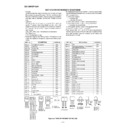
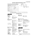
IC701 RH-iX0209AWZZ: FL Driver & Controller (IX0209AW) (2/2)
Port Name
Terminal Name
Pin No.
Input/Output
Function
CD-C3H/CP-C3H
– 61 –
1
VREF
Output
Reference voltage output (Vdda/2)
2
MPXIN
Input
Base band (multiplex) signal input
3
Vdda
—
Analog system power supply (+5V)
4
Vssa
—
Analog system ground
5
FLOUT
Output
Sub-carrier input (comparator input)
6
CIN
Input
Sub-carrier output (filter output)
7
T1
Input
Test input (to be always connected to ground)
8
T2
Input
Test input (standby control)
0: Normal operation/1: Standby state (crystal oscillation stop)
0: Normal operation/1: Standby state (crystal oscillation stop)
9*
T3 (RDCL)
Input/Output
Test I/O (RDS clock output)
10*
T4 (RDDA)
Input/Output
Test I/O (RDS data output)
11 *
T5 (RSFT)
Input/Output
Test I/O (Soft judgment control data output)
12
XOUT
Output
Crystal oscillation output
13
XIN
Input
Crystal oscillation input (external reference signal input)
14
Vddd
—
Digital system power supply
15
Vssd
—
Digital system ground
16*
T6 (ERROR/57K/BE1)
Input/Output
Test I/O (Error existence/nonexistence output/playback carrier output/error block
number output)
number output)
17*
T7 (CORREC/ARI-ID/BE0
Input/Output
Test I/O (Error existence/nonexistence output/SK detection output/error block
number output)
number output)
18*
SYNC
Input/Output
Block sync detection output
19*
RDS-ID
Output
RDS detection output
20
DO
Output
Data output
21
CL
Input
Clock input
Serial data interface (CCB)
22
DI
Input
Data input
23
CE
Input
Chip enable
24
SYR
Input
Sync and RAM address reset (positive logic)
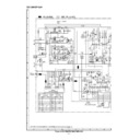
ICT21 VHiLC72720/-1: RDS Microcomputer (LC72720)
Terminal Name
Pin No.
Input/Output
Function
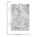
Figure 61 BLOCK DIAGRAM OF IC
In this unit, the terminal with asterisk mark (*) is (open) terminal which is not connected to the outside.
ICT21 VHiLC72720/-1: RDS Microcomputer (LC72720)
Vdda
VREF
VREF
FLOUT CIN
Vssa
Vddd
Vssd
RDS-ID
SYNC
SYR
XOUT
XIN
MPXIN
DO
CL
DI
CE
CL
DI
CE
T1
T2
T3~T7
REFERENCE
VOLTAGE
57kHz
BPF
(SCF)
ANTIALIASING
FILTER
CCB
TEST
SMOOTHING
FILTER
RAM
(24 BLOCK DATA)
ERROR CORRECTION
(SOFT DECISION)
PLL
(57kHz)
CLOCK
RECOVERY
(1187.5Hz)
DATA
DECODER
SYNC
DETECT-1
OSC/DIVIDER
MEMORY CONTROL
CLK(4.332MHz)
SYNC
DETECT-2
SYNC/EC CONTROLLER
1
5
6
3
4
2
20
21
22
23
7
8
9,10,11
16,17
16,17
13
12
24
18
19
15
14
CD-C3H/CP-C3H
– 62 –
G9
G9
G9
G6
G6
G8
G8
G5
G5
G4
G4
G10
G3
G10
G3
G2
G2
G1
G1~G8
G7
G7
S40
S39
S38
S30
S33
S35
S37
S36
S34
S31
S29
S27
S25
S23
S32
S24
S26
S28
S22
S41
S10
S1
S2
S7
S6 S5
S4
S3
S9
S8
S16
S15
S14
S13
S12
S17
S19
S21
S20
S18
S0
S1
S2
S3
S4
S5
S6
S7
S8
S9
S10
S11
S12
S13
S14
S15
S16
S17
S18
S19
S20
G1
S0
S1
S2
S3
S4
S5
S6
S7
S8
S9
EON
RDS
S12
S13
S14
S15
S16
S17
S18
S19
S20
G2
S0
S1
S2
S3
S4
S5
S6
S7
S8
S9
PTY
TA
S12
S13
S14
S15
S16
S17
S18
S19
S20
G3
S0
S1
S2
S3
S4
S5
S6
S7
S8
S9
TI
TP
S12
S13
S14
S15
S16
S17
S18
S19
S20
G4
S0
S1
S2
S3
S4
S5
S6
S7
S8
S9
NR
SLEEP
S12
S13
S14
S15
S16
S17
S18
S19
S20
G5
S0
S1
S2
S3
S4
S5
S6
S7
S8
S9
ON
OFF
S12
S13
S14
S15
S16
S17
S18
S19
S20
G6
S0
S1
S2
S3
S4
S5
S6
S7
S8
S9
PLAY
S12
S13
S14
S15
S16
S17
S18
S19
S20
G7
S0
S1
S2
S3
S4
S5
S6
S7
S8
S9
S10
S12
S13
S14
S15
S16
S17
S18
S19
S20
G8
S0
S1
S2
S3
S4
S5
S6
S7
S8
S9
S12
S13
S14
S15
S16
S17
S18
S19
S20
G9
S0
REC
PS
MEMORY
RANDOM
SRS
X-BASS
1
2
3
4
MHz
kHz
G10
PBC
ONCE
1
2
3
(1)
(1)
(1)
(2)
(2)
(2)
(3)
(3)
(3)
S21
S22
S23
S24
S25
S26
S27
S28
S29
S30
S31
S32
S33
S34
S35
S36
S37
S38
S39
S40
S41
G1
S21
S22
S23
S24
S25
S26
S27
S28
S29
S30
S31
S32
S33
S34
S35
S36
S37
S38
S39
S40
S41
G2
S21
S22
S23
S24
S25
S26
S27
S28
S29
S30
S31
S32
S33
S34
S35
S36
S37
S38
S39
S40
S41
G3
S21
S22
S23
S24
S25
S26
S27
S28
S29
S30
S31
S32
S33
S34
S35
S36
S37
S38
S39
S40
S41
G4
S21
S22
S23
S24
S25
S26
S27
S28
S29
S30
S31
S32
S33
S34
S35
S36
S37
S38
S39
S40
S41
G5
S21
S22
S23
S24
S25
S26
S27
S28
S29
S30
S31
S32
S33
S34
S35
S36
S37
S38
S39
S40
S41
G6
S21
S22
S23
S24
S25
S26
S27
S28
S29
S30
S31
S32
S33
S34
S35
S36
S37
S38
S39
S40
S41
G7
S21
S22
S23
S24
S25
S26
S27
S28
S29
S30
S31
S32
S33
S34
S35
S36
S37
S38
S39
S40
S41
G8
S21
S22
S23
S24
S25
S26
S27
S28
S29
S30
S31
S32
S33
S34
S35
S36
S37
S38
S39
S40
S41
G9
ST
5
15
14
13
12
11
10
9
8
7
6
S34
S35
S36
S37
S38
S39
S40
S41
G10
S21
S22
S23
S24
S25
S26
S27
S28
S29
S30
S31
S32
S33
S34
S35
S36
S37
S38
S39
S40
S41
REC
R
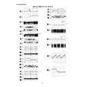
PIN ASSIGNMENT
Pin No.
Assignment
Pin No.
Assignment
4 5 6 7 8 9 10 11 12 13 14 15 16 17 18
NPNL H
G10G9 G8G7G6G5 G4G3G2G1
S0S1
33 34 35 36 37 38 39 40 41 42 43 44 45 46 47
S16S17 S18S19S20 S21S22S23S24 S25S26S27S28 S29S30
48 49 50 51 52 53 54 55 56 57 58 59 60 61
S31S32 S33S34S35 S36S37S38S39 S40S41
D NLNP
19 20 21 22 23 24 25 26 27 28 29 30 31 32
S2S3 S4S5S6 S7S8S9
S10 S11S12S13S14 S15
1~3
F1
62~64
F2
FL701 VVKCK1627M/-1
Figure 62 FL SEGMENT

