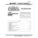
Sharp CD-BA2010 (serv.man4) Service Manual ▷ View online
CD-BA2010H
– 4 –
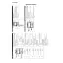
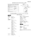
NAMES OF PARTS
CD-BA2010H
Front panel
1
. (CD) Disc Tray
2
. (CD) Disc Skip Button
3
. (CD) Disc Number Select Buttons
4
. (CD) Open/Close Button
5
. Extra Bass Indicator
6
. Spectrum Analyzer/Volume Level Indicator
7
. (CD) Disc Number Indicators
8
. (CD/TUNER) Memory Indicator
9
. (TAPE 2) Record Indicator
10
. (CD) Play Indicator
11
. (CD) Music Schedule Indicators
12
. (CD) More Tracks Indicator
13
. (CD) Pause Indicator
14
. (TAPE) Play Indicator
15
. (CD) Repeat Indicator
16
. Dynamic PTY Indicator
17
. Programme Type Indicator
18
. Traffic Information Indicator
19
. EON Indicator
20
. Traffic Programme Indicator
21
. Sleep Indicator
22
. RDS Indicator
23
. FM Stereo Mode Indicator
24
. Traffic Announcement Indicator
25
. FM Stereo Indicator
26
. Timer Record Indicator
27
. Timer Play Indicator
28
. On/Stand-by Button
29
. Clock Button
30
. Timer/Sleep Button
31
. Dimmer Button
32
. Equalizer Mode Selector Button
33
. Extra Bass/Demo Mode Button
34
. (TUNER) Programme Type/Traffic Information
Search Button
35
. (TUNER) EON Button
36
. (TUNER) ASPM Button
37
. (TUNER) Display Mode Selector Button
38
. (TUNER) Station Selector Button
39
. Volume Control
40
. Headphone Socket
41
. Function Selector Buttons
42
. Tuning and Time Up/Down Buttons
43
. (CD) Track Down/Review Button
(TUNER) Preset Down Button
(TAPE 2) Rewind Button
(TAPE 2) Rewind Button
44
. Memory/Set Button
45
. (CD/TAPE) Stop Button
46
. Timer Set Indicator
47
. (CD) Play/Repeat Button
(TAPE) Play Button
48
. (TAPE 2) Record Pause Button
49
. (CD) Track Up/Cue Button
(TUNER) Preset Up Button
(TAPE 2) Fast Forward Button
(TAPE 2) Fast Forward Button
50
. (TAPE 1) Cassette Compartment
51
. (TAPE 2) Cassette Compartment
– 5 –
CD-BA2010H
Rear panel
1
. AC Power Lead
2
. FM 75 Ohms Aerial Socket
3
. AM Loop Aerial Socket
4
. Speaker Terminals
5
. Video/Auxiliary (Audio Signal) Input Sockets
1
. Woofer
2
. Tweeter
3
. Super Tweeter
4
. Subwoofer
5
. Bass Reflex Duct
6
. Main Speaker (Woofer, Tweeter and Super Tweeter) Wire
7
. Subwoofer Wire
Remote control
1
. Remote Control Transmitter LED
CD control section
2
. Disc Number Select Buttons
3
. Memory Button
4
. Pause Button
5
. Clear Button
6
. Track Down/Review Button
7
. Track Up/Cue Button
8
. Disc Skip Button
9
. Play/Repeat Button
10
. Stop Button
11
. Random Button
Tuner control section
12
. Preset Up/Down Buttons
Tape control section
13
. (TAPE 1) Play Button
14
. (TAPE 2) Record Pause Button
15
. (TAPE 1/2) Stop Button
16
. (TAPE 2) Play Button
17
. (TAPE 2) Rewind Button
18
. (TAPE 2) Fast Forward Button
Common section
19
. Equalizer Mode Selector Button
20
. Function Selector Buttons
21
. On/Stand-by Button
22
. Extra Bass Button
23
. Volume Up/Down Buttons
CP-BA2010H
CD-BA2010H
– 6 –
OPERATION MANUAL
SETTING THE CLOCK
In this example, the clock is set for the 24-hour (0:00) system.
1
Press the ON/STAND-BY button to enter the stand-by mode.
2
Press the CLOCK button.
3
Within 5 seconds, press the MEMORY/SET button.
4
Press theTUNING/TIME ( or ) button to select the time
display mode.
“0:00”
→
The 24-hour display will appear.
(0:00 - 23:59)
“AM 0:00”
→
The 12-hour display will appear.
(AM 0:00 - PM 11:59)
“AM 12:00”
→
The 12-hour display will appear.
(AM 12:00 - PM 11:59)
Note that this can only be set when the unit is first in-
stalled or it has been reset.
5
Press the MEMORY/SET button.
6
Press the TUNING/TIME ( or ) button to adjust the hour.
Press the TUNING/TIME ( or ) button once to ad-
vance
the time by 1 hour
. Hold it down to advance con-
tinuously
.
When the 12-hour display is selected, “AM” will change
automatically to
“PM”.
7
Press the MEMOR
Y/SET
button.
8
Press the
TUNING/TIME (
or
) button to adjust the min-
utes.
Press the
TUNING/TIME (
or
) button once to ad-
vance
the time by 1 minute. Hold it down to change the
time in 5
minute intervals.
The hour setting will not advance even if minutes advance
from “59” to “00”.
9
Press the MEMOR
Y/SET
button.
The clock starts operating from “0” second.
(Seconds are not displayed.)
And then the clock display will disappear after a few sec-
onds.
T
o
see the time display:
Press the CLOCK button.
The time display will appear for about 5 seconds.
Note:
The clock display will flash on and of
f at the push of the
CLOCK button when the
AC power supply is restored after
a power failure occurs or after the
AC power lead is discon-
nected.
If this happens, follow the procedure below to change the
clock time.
T
o
change the clock time:
1
Press the CLOCK button.
2
Within 5 seconds, press the MEMOR
Y/SET
button.
3
Perform steps 6 - 9 above.
T
o
change the time display mode:
1
Perform steps 1 - 2 in the section “RESETTING
THE
MICROCOMPUTER”.
2
Perform steps 1 - 9 above.
(Main unit operation)
REMOTE CONTROL
0.2 m - 6 m
(8" - 20’)
Notes concerning use:
Replace the batteries if the operating distance is reduced or
if the operation becomes erratic.
Periodically clean the transmitter LED on the remote con-
trol and the sensor on the main unit with a soft cloth.
Exposing the sensor on the main unit to strong light may
interfere with operation. Change the lighting or the direction
of the unit.
Keep the remote control away from moisture, excessive heat,
shock, and vibrations.
RESETTING THE MICROCOMPUTER
Reset the microcomputer under the following con-
ditions:
T
o
erase all of the stored memory contents (clock and timer
settings, and tuner and CD presets).
If the display is not correct.
If the operation is not correct.
1
Press the ON/ST
AND-BY
button to enter the stand-by mode.
2
Whilst pressing down the
/
button and the X-BASS/
DEMO
button, hold down the ON/ST
AND-BY
button for at
least 1 second.
“CLEAR
AL” will appear
.
Caution:
The operation explained above will erase all data stored in
memory including clock and timer settings, and tuner and
CD presets.
– 7 –
CD-BA2010H
Chec
k the supplied accessories
AM loop aerial
×
1
FM aerial
×
1
Remote control
×
1
Putting batteries into the remote contr
ol
Placing the system
10 cm (4")
10 cm (4")
10 cm (4")
10 cm (4")
2 "
A
A
" size
ba
tt
er
ies
(UM/SUM-3, R6, HP-7 or similar)
1
Remo
ve the battery co
ver
.
2
Inser
t the batteries.
3
Replace the batter
y co
ver
.
1
2
3
Connections
4
AM loop
aerial
AC 230 V, 50 Hz
[For U.K.]
[Except for U.K.]
1
Connect the AM and FM aerials.
2
Connect the speaker system.
Blue
Red
Black
3
Connect the A
C
po
wer lead.
Right speaker
Left speaker
FM aerial
1
2

