Sharp AY-X10 (serv.man16) Service Manual ▷ View online
3
AH/AY-X08CR
AH/AY-X10CR
AH/AY-X13CR
AH/AY-X10CR
AH/AY-X13CR
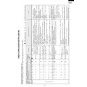
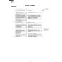
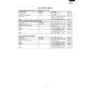
MODEL
INDOOR UNIT OUTDOOR UNIT INDOOR UNIT OUTDOOR UNIT INDOOR UNIT OUTDOOR UNIT
ITEMS
AY-X08CR AE-X08CR AY-X10CR AE-X10CR AY-X13CR AE-X13CR
Cooling capacity(Min. ~ Max.) kW
2.2(0.9 _ 2.7)
2.8(0.9 _ 3.3)
3.6(0.9 _ 4.0)
Heating capacity(Min. ~ Max.) kW
3.2(0.9 _ 3.6)
3.7(0.9 _ 5.0)
4.8(1.0 _ 6.2)
Moisture removal(at cooling) Liters/h
0.7
0.8
1.3
Electrical data
Phase
Single
Rated frequency
Hz
50
Rated voltage range
V
198 to 264
Rated voltage
V
220 - 240
Cool
A
3.4 _ 3.1
4.3 _ 4.0
5.5 _ 5.1
Rated current
Heat
A
4.2 _ 3.9
4.9 _ 4.5
6.8 _ 6.2
Cool
W
730
930
1200
Rated input
Heat
W
910
1050
1480
Cool
%
98 _ 98
98 _ 97
99 _ 98
Power factor
Heat
%
98 _ 97
97 _ 97
99 _ 99
Type
Hermetically sealed rotary type
Compressor
Model
DA89X1F-20F
Oil charge
Ester oil VG68 370ml
Evaporator
Louver Fin and Grooved tube type
Refrigerant system Condenser
Corrugate Fin and Grooved tube type
Control
Capillary tube
Refrigerant volume
750g
770g
870g
(R-410A)
De-lce system
Micro computer controled reversed systems
Noise level
High
dB(A)
33
43
36
43
38
48
(at cooling)
Med.
dB(A)
29
–
32
–
33
-
Low
dB(A)
27
–
27
–
29
-
Fan system
Drive
Direct drive
Air flow quantity
High
m
3
/min.
7.5
28
9.8
27.7
9.3
30
(at cooling)
Med.
m
3
/min.
6.8
–
8.2
–
8.1
–
Low
m
3
/min.
6.0
–
6.1
–
6.6
–
Fan
Cross flow fan Propeller fan Cross flow fan Propeller fan Cross flow fan Propeller fan
Connections
Refrigerant coupling
Flare type
Refrigerant tube size Gas, Liquid
3/8", 1/4"
Drain piping mm
O.D ø 18
Others
Compressor: Compressor thermistor
Safety device
Fan motors: Thermal fuse
Fuse, Micro computer control
Air filters
Polypropylene net (Washable)
Width
mm
815
780
815
780
815
780
Net dimensions
Height
mm
278
540
278
540
278
540
Depth
mm
198
269
198
269
198
269
Net weight
kg
9
33
10
33
10
37
Note: The condition of star "
" marked item are ‘ISO5151’ : 1994(E), condition T1.
4
AH/AY-X08CR
AH/AY-X10CR
AH/AY-X13CR
AH/AY-X10CR
AH/AY-X13CR
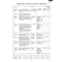
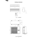
EXTERNAL DIMENSIONS
Figure E-1. INDOOR UNIT
Figure E-2. OUTDOOR UNIT
Length unit (mm)
815
278
198
1100
Remote controller
58
18.5
22
140
INVERTER AIR CONDITIONER
269
179.5
182.5
136
81
780
70
540
310
335
540
12
37.5
4.5
58
158
16
5
AH/AY-X08CR
AH/AY-X10CR
AH/AY-X13CR
AH/AY-X10CR
AH/AY-X13CR
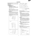
Figure E-3. INSTALLATION DIMENSIONS
815 (unit size)
More than 50mm
E
Center of wall hole:
Leftward piping
Leftward piping
Center of wall hole: Backward piping
Outline of indoor unit
55
95
80
55
A
J
I
F
E
D
D
F
A
C
J
H
I
G
B
21
278 (unit size)
38
Ceiling
E
6
AH/AY-X08CR
AH/AY-X10CR
AH/AY-X13CR
AH/AY-X10CR
AH/AY-X13CR
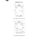
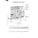
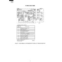
WIRING DIAGRAMS
Figure W-1. Wiring Diagram for AH-X08CR/X10CR/X13CR and AY-X08CR/X10CR/X13CR
BROWN
RY1
In
Out
CB612-1
10
7
8
8
6
Temperature
Indicator
Blinking No.
Indicator
Blinking No.
Abnormal contents
AC overcurrent
Abnormal AC current
WPE1
250V
3A
INDOOR UNIT
UNIT
TO
UNIT
CORD
Power factor module(AF1) error
13
Overheat of the power module(IPM) or
short circuit of the power module(IPM) heat-sink thermistor
short circuit of the power module(IPM) heat-sink thermistor
Open circuit of the power module(IPM) heat-sink thermistor
Rotation error of the compressor
OUTDOOR UNIT
N
1
2
TERMINAL BOARD
CONTROL BOARD UNIT
POWER
SUPPLY
TERMINAL BOARD 2
SINGLE
PHASE
N
1
2
CONTROL
BOARD
UNIT
M
M
FAN MOTOR
COMPRESSOR
N
1
TERMINAL BOARD 1
M
M
LOUVER
(LOWER)
SERIAL
SIGNAL
CIRCUIT
BLUE
BLUE
BLACK
S
RED
N
INTERNAL
THERMAL
FUSE
RECEIVER
BOARD UNIT
R.P.M.
SIGNAL
FAN MOTOR
CAPACITOR
430V 2.0
µ
F
FAN MOTOR
LOUVER
(UPPER)
1
3
TH1
5
CN1
BCN1
BCN3
BCN2
CN2
CN3
TH2
YELLOW
ORANGE
CN6
CN7
DISPLAY
BOARD
UNIT
CN101
CN102
ROOM TEMP.
THERMISTOR
THERMISTOR
PIPE TEMP.
THERMISTOR
THERMISTOR
GREEN-YELLOW
TRANS1
SSR1
1
3
4
2
RED
BLUE
BLACK
C1
LED INDICATION FOR SELF-DIAGNOSIS
5
2
3
3
1
14
17
18
19
Short circuit of the outdoor thermistor
Overheat of the compressor
Open circuit of the outdoor thermistor
Power module(IPM) abnormality
Open circuit of serial signal line
Abnormal fan motor of indoor unit
Short circuit of serial signal line
CB612-2
<Indication of the abnormal condition>
LED indicator will blink,if the set
is in abnormal condition.
LED indicator will blink,if the set
is in abnormal condition.

