Sharp AY-AP18 (serv.man11) Service Manual ▷ View online
31
AY-AP18CS
AY-AP24CS
AE-A18CS
AE-A24CS
AY-AP24CS
AE-A18CS
AE-A24CS
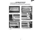
The Electric Control box.
1.
Remove the screw fixing the Receiving filter.
2.
Remove the 2 Switch and Photo detector unit.
3.
Remove a screw fixing the Cord holder.
4.
Remove a screw fixing the Cord holder and 2
screws fixing the Terminal board.
screws fixing the Terminal board.
5.
Remove 2 screws fixing the Transformer and pull
the Control board unit.
The DRAIN PAN and related
the Control board unit.
The DRAIN PAN and related
AY-AP18CS
AY-AP24CS
AE-A18CS
AE-A24CS
AY-AP24CS
AE-A18CS
AE-A24CS
32
The LOUVER FRAME UNIT and related
1.
1.
Remove the screw fixing the FRAME GUIDE on
both side and take off the LOUVER UNIT.
2.
Remove 2 screws fixing Cover-L and Cover-R
and take off them.
33
AY-AP18CS
AY-AP24CS
AE-A18CS
AE-A24CS
AY-AP24CS
AE-A18CS
AE-A24CS
1
2
3.
Remove the connector of Louver motor and take
off the Wire and Holder.
off the Wire and Holder.
4.
Push the one of the Vertical louver.
How to remove the DISPLY COVER.
1
Push the center of the Front panel under
the Display cover.
the Display cover.
2
Slide it to one side.
How to remove the Hi Voltage UNIT.
1.
Remove 2 screws fixing Holder.
2.
Take off the HIGH VOLTAGE UNIT ASS’Y from
the HOLDER
the HOLDER
3.
Remove the connector of HIGH VOLTAGE UNIT
ASS’Y
ASS’Y
AY-AP18CS
AY-AP24CS
AE-A18CS
AE-A24CS
AY-AP24CS
AE-A18CS
AE-A24CS
34
FOR OUTDOOR UNIT MODEL AE-A18CS / AE-A24CS
DISASSEMBLING PROCEDURE OF THE CONTROL BOX
1.
Loose 3 screws fixing the control cover.
2.
Loose 1 screw fixing the side cover.
3.
Loose 8 screws fixing the side cover R.
4.
Loose 2 screws fixing the cabinet (left side).
5.
Loose 1 screw fixing the cabinet (rear side).
6.
Loose 3 screw fixing the cabinet (right side).
7.
Loose 1 screw fixing the cabinet (front side).
8.
Loose 7 screws fixing the rear cabinet.
Click on the first or last page to see other AY-AP18 (serv.man11) service manuals if exist.

