Sharp AU-X08 (serv.man10) Service Manual ▷ View online
29
AH/AY-X08CR
AH/AY-X10CR
AH/AY-X13CR
AH/AY-X10CR
AH/AY-X13CR
100
80
60
40
20
0
-10
0
10
20
30
40
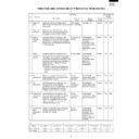
Resistance
Thermistor
Room temperature
Heat exchange
Color
Yellow
Orange
To measure the resistance, first remove
the connector as shown at right.
Room temperature
thermistor TH1
Tester
Signal
CN7
CN7
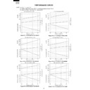
Figure 1 Temperature properties of indoor thermistors
500K
400K
300K
200K
100K
0
-20
0
20
60
80
100
120
3.06K
5.78K
4.17K
2.28K
1.72K
16
40K
30K
20K
10K
0
-20
0
20
60
40
16
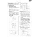
Figure 3 Temperature properties of outdoor thermistors
Connector
CN8
TH2 Heat exchange thermistor
TH3 Outdoor temp. thermistor
TH1 compressor thermistor
TH2,TH3
Connector
CN8
Temperature (
°
C)
Temperature (
°
C)
Tester
Tester
Thermistor
To measure the
resistance, first
remove the
connector from the
board.
Color
No.
Connector
Compressor
thermistor
Heat exchanger
pipe thermistor
Outdoor temp.
thermistor
TH1
TH2
TH3
No. 1 to 2
No. 3 to 4
Red
Orange
No. 5 to 6
Green
Microcomputer
terminal
Input
signal
To Outdoor control board
Adaptor
(R22)
(GND)
(R16)
Pin No. 27
Pin No. 28
0
1
0 Low input
1 High input
K
Heat exchange thermistor
TH2 (orange)
25
°
C resistance 15 K
Room temperature
thermistor TH1 (yellow)
25
°
C resistance 10 K
25
°
C resistance
45 K
Resistance ( )
Resistance ( )
0
°
C resistance
14.5 K
25
°
C resistance
4.431 K
Figure 2 Temperature properties of heatsink thermistors
Heat exchange
thermistor TH2
Tester
41
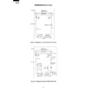
Cautions when attaching or removing the board
When oper
ating only the outdoor unit (cooling 40 Hz fix
ed mode)
T
o
mak
e
only the outdoor unit r
un in cooling mode
, shor
t the places mar
k
ed with
arro
ws belo
w with an adaptor
, and apply a v
oltage of 220 ~ 240
V A
C
to 1
and N on the ter
minal board.
(A
v
oid oper
ating the outdoor unit alone f
or long per
iods of time
.)
500
400
300
200
100
0
-20
0
20
40
Temperature (˚C)
80
100
3.25k
60
12.3k
6.14k
Resistance (k )
Thermistor
Heatsink
Color
Black
To measure the resistance, first remove
the connector as shown at right.
Signal
CN7
Heatsink thermistor
TH6 (black)
25
°
C resistance 50k
Tester
1
3
Display

