Sharp AU-A18 (serv.man7) Service Manual ▷ View online
AH-AP18CS
AH-AP24CS
AU-A18CS
AU-A24CS
AH-AP24CS
AU-A18CS
AU-A24CS
12
FUNCTIONS
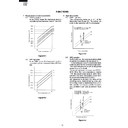
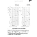
1. Temperature control characteristic
1-1
COOL operation
In the “COOL” mode, the thermostat circuit is
controlled by four thermostat lines (C1 thru C5).
In the “COOL” mode, the thermostat circuit is
controlled by four thermostat lines (C1 thru C5).
2. Operation modes
2-1
COOL operation
The compressor turns on or off, at the
thermostat lines C3 and C4. The outdoor fan
motor is also controlled with the compressor.
The compressor turns on or off, at the
thermostat lines C3 and C4. The outdoor fan
motor is also controlled with the compressor.
Figure H-1
1-2
DRY operation
In the “DRY” mode, the thermostat circuit is
controlled by three thermostat lines (D1 thru
D3).
In the “DRY” mode, the thermostat circuit is
controlled by three thermostat lines (D1 thru
D3).
Figure H-3
2-2
DRY operation
On the switch on, the compressor always starts
to operate for 2 minutes with fan speed “DL” .
The microcomputer reads the room temperature
2 minutes after this first compressor operation.
This room temperature is set as the preset
temperature automatically.
The preset temperature ranges from 18˚C to
32˚C. When the room temperature is below
18˚C, the preset temperature is set to 18˚C,
and when the room temperature is over 32˚C,
the preset temperature is set to 32˚C.
Dry operation is divided into three zones
(Cooling zone, Dehumidifying zone and
Circulating zone) by thermostat lines (D1 to
D3), and the compressor and the fan motor
are controlled in each zone as shown in Table
H-1.
Figure H-2
Figure H-4
Room temperature(˚C)
Preset temperature (˚C)
18
32
D1
D2
D3
17.5
18.5
19.5
31.5
32.5
33.5
Room temperature
Preset temperature
Room
temperature
transition
temperature
transition
C4
C5
States 1 & 3 : Compressor ON
State 2 : Compressor OFF
State 2 : Compressor OFF
1
2
3
Room temperature
Preset temperature
Room
temperature
transition
temperature
transition
D3
D2
D1
States 1 & 5 : Cooling zone
States 2 & 4 : Dehumidifying zone
States 3 : Circulating zone
States 2 & 4 : Dehumidifying zone
States 3 : Circulating zone
3
4
5
1
2
18
32
C1
C2
C4
C3
C5
17.5
18.5
19.0
19.5
20.5
31.5
32.5
33.5
34.5
Preset temperature (˚C)
Room temperature (˚C)
13
AH-AP18CS
AH-AP24CS
AU-A18CS
AU-A24CS
AH-AP24CS
AU-A18CS
AU-A24CS
Room temperature
Preset temperature
R o o m
t e m p e r a t u r e
t e m p e r a t u r e
t r a n s i t i o n
C3
C2
C1
S t a t e s 1 & 5 : " C A H "
S t a t e s 2 & 4 : " C M "
S t a t e s 3 : " C A L "
S t a t e s 2 & 4 : " C M "
S t a t e s 3 : " C A L "
a . C O O L o p e r a t i o n
3
4
5
1
2
Table H-1
3. Fan speed
Fan speeds are given by the indoor fan motor,
"DL"~"CH" which are available in the following
operation mode.
"DL"~"CH" which are available in the following
operation mode.
Table H-2
NOTE:Fan speed may be changed, without warning.
Compressor
Cooling zone 1 & 5
Dehumidifying zone 2 & 4
Circulating zone 3
Fan speed
ON
"DH"
"DL"
"DL" or OFF
ON
OFF
4. Freeze preventive
When the indoor pipe temperature falls below 0˚C
cool or dry operation for 3 minutes or more, the
compressor is turned off. When the indoor pipe
temperature rises above 4˚C in cool or dry operation for
3 minutes or more, the compressor is turned on.
cool or dry operation for 3 minutes or more, the
compressor is turned off. When the indoor pipe
temperature rises above 4˚C in cool or dry operation for
3 minutes or more, the compressor is turned on.
5. Test run
If the "AUX" button on the unit is pressed for 5 seconds
or more during operation, cool test operation starts.
The operation LED (red) flickers during test run.
In cool mode continuous compressor on operation is
performed. In dry mode the operation is in dehumidifying
zone.
or more during operation, cool test operation starts.
The operation LED (red) flickers during test run.
In cool mode continuous compressor on operation is
performed. In dry mode the operation is in dehumidifying
zone.
6. Timer
6-1
ON/OFF TIMER
When the unit operates during one hour after
the OFF-time is set, thermostat setting is
automatically shifted (+1˚C in cool operation
and dry operation). When the ON-timer is set
in cool operation, operation starts before 0 to
30 minutes(depends on the room temperature)
so that preset temperature is obtaind at set
time.
6-2
ONE-HOUR TIMER
When ONE-HOUR timer is set, the unit turns
off automatically after one hour. The one hour
timer operation has priority over other time
operation, such as the TIMER ON and TIMER
OFF. If the ONE-HOUR TIMER button is
pressed again during operation, the unit will
operate additionally for another one hour.
7. Automatic air conditioning
When automatic air conditioning is selected, the
operation mode and preset temperature are set
automatically according to the room temperature on
starting operation.
operation mode and preset temperature are set
automatically according to the room temperature on
starting operation.
Table H-3
When DRY mode is selected by the micro computer
with AUTO operation, the fan speed lamps on the
indoor unit panel will indicate identically with the fan
speed symbols on the remote control dispaly, as the
FAN speed setting is changed accordingly. Despite,
the actual fan speed will not change, as it is determined
automatically by the micro computer.
8. Automatic fan speed
When the automatic fan speed is selected in cool
operation, the fan speed is automatically changed by
the thermostat lines C1 to C3 in cool operation.
operation, the fan speed is automatically changed by
the thermostat lines C1 to C3 in cool operation.
Room temperature
at operation start
at operation start
Operation
Mode
Mode
Preset
Temperature
Temperature
Above 28˚C
26˚C
26˚C ~ 28˚C
24˚C ~ 26˚C
Below 24˚C
25˚C
24˚C
Room temperature
at operation start
at operation start
COOL
DRY
Figure H-5
Fan
switch
DL
Fan
speed
speed
Fan switch
(AUTO)
AH-
AP18CS
(r.p.m.)
750
830
780
860
820
960
840
980
940
1030
1000
1120
1050
1210
AH-
AP24CS
(r.p.m.)
DH
DRY
COOL
CL
COOL
LOW
CAL
CM
COOL
MID
CAH
CH
COOL
HIGH
AH-AP18CS
AH-AP24CS
AU-A18CS
AU-A24CS
AH-AP24CS
AU-A18CS
AU-A24CS
14
Indoor
fan motor
fan motor
Thermistor
short state
short state
Thermistor
open state
open state
Timer
LED
LED
ON
OFF
ON
OFF
ON
OFF
ON
OFF
Operation
LED
LED
Operation
LED
LED
Operation
LED
LED
1sec.
1sec.
4sec.
9. Outputs in each operation mode
Table H-4
10. Power on start
If the connecting wire "JP5 is shorten the PWB ass'y,
when the power is supplied by turning on a circuit
breaker, the air conditioner automatically starts of
operation in "AUTO".
(Refer to Figure L-2, L-4. Printed Wiring Board)
when the power is supplied by turning on a circuit
breaker, the air conditioner automatically starts of
operation in "AUTO".
(Refer to Figure L-2, L-4. Printed Wiring Board)
11. AUTO RESTART
Power failure occurs during operation, the unit will
restart in the same operation mode as before power
recovery.
restart in the same operation mode as before power
recovery.
12.Test mode
Keep pushing the "AUX." buttons and supply the
power, the system will go to the test mode. In this
mode, the output of operation is switched by pushing
the ""AUX." button in the unit or the "OI" button in the
remote controller. Normal outputs are shown in Table
H-5.
power, the system will go to the test mode. In this
mode, the output of operation is switched by pushing
the ""AUX." button in the unit or the "OI" button in the
remote controller. Normal outputs are shown in Table
H-5.
ON
OFF
ON
OFF
ON
ON
ON
ON
OFF
OFF
ON
OFF
ON
L/UL
UL/D
OFF
D/OFF
OFF
OFF
OFF
Mode
Compressor
Outdoor
Fan Motor
Cooling
Circulating
Indoor
Fan Motor
Valve
Coil
C
O
O
O
O
L
D
R
Y
R
Y
Cooling
Circulating
Dehumidiflying
13.Diagnosis procedure
When indoor fan motor is out of order or compressor lock occurs, the compressor, indoor fan motor, outdoor fan
motor, and louver are all stopped and the operation LED(red) turns on or off synchronously with the timing of the
timer LED.
When the thermistor for room temperature or pipe temperature is open or short state, the operation LED turns on
or off synchronously with the timing of the timer LED by pushing continously for more than 5 seconds "AUX."
button during suspension of operation.
Timing chart of Timer LED and Operation LED of DIAGNOSIS PROCEDURE.
When "OI" button the remote controller or "AUX." button in the unit is pushed, the unit is free from DIAGNOSIS
PROCEDURE.
When "OI" button the remote controller or "AUX." button in the unit is pushed, the unit is free from DIAGNOSIS
PROCEDURE.
When the louver unit is not properly installed, all lamps on the indicaor panel will blink.
Operation are all stop and remote signal is not accept.
Operation are all stop and remote signal is not accept.
14.Plasma Cluster
Timer LED
(Yellow)
Judgement
ON
Normal
(Generator OK)
OFF
Failure
(Check circuit)
Cluster generator checking (step 1)
1
Plasma Cluster ion mode
Minus ion mode
SSR2
ON
ON
Relay
(Cluster unit inside)
OFF
ON
15
AH-AP18CS
AH-AP24CS
AU-A18CS
AU-A24CS
AH-AP24CS
AU-A18CS
AU-A24CS
Table H-5
AH-AP18CS
7
~
42˚C
ON
-2
~
45˚C
ON
~
7˚C , 42˚C
~
OFF
~
-2˚C , 45˚C
~
OFF
0.3V
~
4.5V
ON
~
0.3V , 4.5V
~
ON
0.3V
~
4.5V
ON
~
0.3V , 4.5V
~
ON
~
0.3V , 4.5V
~
OFF
0.3V
~
4.5V
OFF
~
0.3V , 4.5V
~
OFF
0.3V
~
4.5V
OFF
OFF
ON
ON
OFF
STEP
No
Buzzer
Lam
p
s
Cluster
Outdoor
Indoor
Fan
Louver
RED
YELLOW
FAN SOFT
FAN LOW
FAN HIGH
FAN AUTO
CLUSTER
Power
Selector
02
Room temp.
Pipe temp.
ON
ON
ON
ON
BLUE
OFF
OFF
OFF
OFF
OPEN
11
FEED BACK CIRCUIT
CT INPUT(AN2 input voltage)
BLUE
ON
OFF
ON
1000
rpm
OFF
OFF
OFF
OPEN
FLICK
21
Power On Start(JP5)
Wireless(JP4)
MODEL SELECTION(AN4 input voltage)
GREEN
ON
ON
OFF
31
Sweat(JP3)
Hot Keep(JP2)
Out Fan(JP18)
TEST(JP8)
Cluster(JP19)
Dry Fan(JP11)
OFF
OFF
OFF
OFF
41
DEICE 1
DEICE 2
Louver Collection(AN5 input voltage)
OFF
OFF
OFF
OFF
51
Pipe 1
Pipe 2
Cooling mode FAN speed Collection(AN6 input voltage)
OFF
OFF
OFF
OFF
OFF
61
EEPROM
Micro SW
Heating mode FAN speed Collection(AN6 input voltage)
OFF
OFF
OFF
OFF
OFF
ON
71
OFF
OFF
EEPROM VERSION(UPPER 4bit)
OFF
OFF
OFF
OFF
OFF
OFF
OFF
OFF
OFF
OFF
OFF
OFF
81
OFF
OFF
CLOSE
OFF
OFF
OFF
OFF
OFF
OFF
EEPROM VERSION(LOWER 4bit)
ON
ON
ON
ON
ON
OFF
ON
ON
ON
ON
OFF
OFF
OFF
OFF
ON
OFF
OFF
OFF
OFF
OFF
ON
ON
ON
ON
AH-AP24CS
7
~
42˚C
ON
-2
~
45˚C
ON
~
7˚C , 42˚C
~
OFF
~
-2˚C , 45˚C
~
OFF
0.3V
~
4.5V
ON
~
0.3V , 4.5V
~
ON
0.3V
~
4.5V
ON
~
0.3V , 4.5V
~
ON
~
0.3V , 4.5V
~
~
0.1V, 4.9V
~
OFF
OFF
0.3V
~
4.5V
OFF
~
0.3V , 4.5V
~
OFF
0.3V
~
4.5V
OFF
OFF
ON
OFF
ON
ON
OFF
ON
ON
ON
OFF
ON
ON
ON
OFF
OFF
ON
ON
OFF
ON
ON
ON
OFF
OFF
OFF
ON
ON
OFF
OFF
NONE
USE
ON
ON
OFF
ON
OFF
ON
ON
OFF
OFF
OFF
FAN HIGH
FAN AUTO
Cluster
STEP
No
Buzzer
Lamps
RED
YELLOW
FAN SOFT
FAN LOW
CLUSTER
Power
Selector
OFF
Outdoor
Indoor
Fan
Louver
BLUE
OFF
OFF
OPEN
OFF
02
Room temp.
Pipe temp.
ON
ON
ON
ON
OFF
OFF
OFF
OFF
OFF
OFF
EEPROM VERSION(UPPER 4bit)
OFF
81
OFF
OFF
OFF
OFF
OFF
EEPROM VERSION(LOWER 4bit)
OFF
OFF
OFF
OFF
OFF
OFF
11
FEED BACK CIRCUIT
CT INPUT(AN2 input voltage)
BLUE
ON
OFF
ON
1000
rpm
OFF
OFF
OPEN
FLICK
21
Power On Start(JP5)
Wireless(JP4)
MODEL SELECTION(AN4 input voltage)
GREEN
ON
ON
OFF
31
Hot Keep(JP2)
Out Fan(JP18)
TEST(JP8)
Cluster(JP19)
Dry Fan(JP11)
OFF
OFF
41
DEICE 2
Louver Collection(AN5 input voltage)
OFF
OFF
OFF
OFF
OFF
51
Pipe 2
Cooling mode FAN speed Collection(AN6 input voltage)
OFF
OFF
OFF
61
EEPROM
Micro SW
Heating mode FAN speed Collection(AN6 input voltage)
OFF
OFF
OFF
ON
71
OFF
CLOSE
OFF
OFF
OFF
OFF
OFF
OFF
OFF
AN3 ( 1)
0.1V
~
4.9V
ON
~
0.1V, 4.9V
~
OFF
0.1V
~
4.9V
ON
AN3 ( 1)
ON
OFF
NONE
USE
Display

