Sharp AE-XM24CR (serv.man10) Service Manual ▷ View online
43
AY-XM7/9/12CR
AY-XPM7/9/12CR
AE-XM18/24CR
AY-XPM7/9/12CR
AE-XM18/24CR
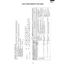
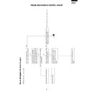
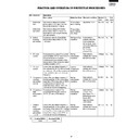
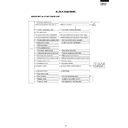
BREAK DOWN DIAGNOSIIS PROCEDURES
: Blinks at 1-second intervals
: OFF
: ON
: Blinks 3 times at 0.1-second intervals
Indoor and outdoor unit
completely stopped
Display by indoor unit operation lamp
Displayed in a pattern which comes on at the
same time as the timer lamp
4 seconds off
What to check, procedure
Display by
outdoor
unit lamp
LED
51 ~ 52
Diagnosis
Solution
Condition
of indoor
and
outdoor
unit
Normal
Twice
Temp.
indicator
3 times
4 times
Power module(IPM)
abnormality
Normal
1. Check the circuit in the power transistor module.
2. Is the outdoor fan revolving ?
1. Measure the resistance of thermistor TH2, TH3, TH4, TH5,
TH6, TH7 on the outdoor unit (see Figure 2).
1. Replace power transistor
module
2. Replace power transistor the
outdoor fan motor or fan
capacitor.
Overheat of the
comp-ressor error
(protector operating)
or outdoor
compressor
thermistor TH1 short
1.Replace the outdoor thermistor
assembly. (RH-HXA024JBZZ or
RH-HXA022JBZZ
1.Clear the discharge outlet.
2.Assure power supply voltage.
3.Refill to rated amount.
4.Replace the outdoor thermistor
assembly. (RTHM-A022JBE0)
5.Replace the indoor thermistor
assembl.
(RH-HXA023JBZZ)
1. Is the discharge outlet of the outdoor unit clogged ?
2. Is the power supply voltage at least 207 V at full power
operation ?
3. Check for refrigerant leaks at the tubing connections.
4. Measure the resistance of compressor thermistor TH1 on
the outdoor unit (see Figure 2).
5. Measure the resistance of heat exchanger pipe thermistor
TH2 on the indoor unit (see Figure 1).
Short circuit of the
thermistor error
0.5
sec..
0.5
sec
0.5
sec.
0.5
sec.
0.5
sec.
0.5
sec.
0.5
sec.
0.5
sec.
0.5
sec.
0.5
sec.
0.5
sec.
0.5
sec.
0.5
sec.
0.5
sec.
0.5
sec.
0.5
sec.
0.5
sec.
0.5
sec.
0.5
sec.
0.5
sec.
0.5
sec.
0.5
sec.
0.5
sec.
0.5
sec.
1 time
Compressor lock
Overheat of the compressor
2 times
ON
OFF
ON
OFF
Self-diagnostic procedure using display mode
If the timer lamp and operation lamp blinks during operation, the problem can be diagnosed using the following table.
Note: 1. The breakdown diagnossis can be diagnosed by the LED lamps by pushing the "AUX." button for 5 seconds
or more while operation stops.
Normal : Only the timer lamp blinks. Error : Displayed by combined blinking of operation lamp and
timer lamp (below table).
2. If the breaker is switched to "OFF", the self-diagnostic
memory will be erased.
3. Example of outdoor unit LED 50 ~ 52 blinking :
44
AY-XM7/9/12CR
AY-XPM7/9/12CR
AE-XM18/24CR
AY-XPM7/9/12CR
AE-XM18/24CR
: Blinks at 1-second intervals
: OFF
: ON
: Blinks 3 times at 0.1-second intervals
Indoor and outdoor unit
completely stopped
Display by indoor unit operation lamp
Displayed in a pattern which comes on at the
same time as the timer lamp
4 seconds off
What to check, procedure
Display by
outdoor
unit lamp
LED
51 ~ 52
Diagnosis
Solution
Condition
of indoor
and
outdoor
unit
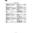
5 times
6 times
7 times
AC overcurrent error
1. Is the discharge outlet of the outdoor unit clogged ?
1. Clear the discharge outlet.
8 times
Abnormal wire check
1. Check the attached point CN8B of outdoor unit.
2. Measure the resistance value of thermistor TH5, TH6, TH7
of outdoor unit.
3. Check the expansion valve. (unit A, unit B, unit C)
4.
Are four expansion valves connected by mistake ?
5. Check the wiring between units.
1.Reattach
2.Replace the outdoor thermistor
assembly. (TH5, TH6, TH7)
3.Replace the outdoor control
board assembly.
4. Reattach
5. Check the wiring between units.
6. Check the incorrect wiring.
(When connection between the
units is wrong as follows)
1.Replace Power module (IPM)
2.Replace the outdoor Power
supply P.W.B..
3.Rewire
1.Replace Power factor module
(AF1)
1.Replace the outdoor control
board assembly (Current
transformer is broken.)
1.Reattach.
2.
Replace the outdoor thermistor
assembly. (RTHM-A022JBE0)
or (RH-HXA024JBZZ or
RH-HXA022JBZZ )
1. Can voltage be detected at the current transformer on the
outdoor unit control board?
1. Are the connectors of the outdoor unit thermistors well
attached ?
2. Measure the resistance of thermistors TH1, TH2, TH3,
TH4, TH5, TH6, TH7 on the outdoor unit (see Figure 2).
AC abnormal current
error
Open circuit of the
thermistor error
A
B
Indoor unit
Outdoor unit
UNIT A
UNIT B
C
UNIT C
(Example)
Terminal
board
9 times
Rotation error of the
compressor
1. Check the voltage (18V) between BCN14 3 and 4
2. Check the compressor terminal and Power module terminal
RED : S(COMP), U(IPM), WHITE : C(COMP), V(IPM),
ORANGE : R(COMP), W(IPM)
11 times
Power factor module
(AF1) error
1. Check the resistance value among the terminal of the
power factor module (L - and OUT -)
45
AY-XM7/9/12CR
AY-XPM7/9/12CR
AE-XM18/24CR
AY-XPM7/9/12CR
AE-XM18/24CR
Indoor unit
operating
Outdoor unit
completely stopped
Serial short
Serial open
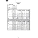
1. Check the wiring between units.
1. Check the wiring between units.
1. Check the wiring between units.
2. Check the fuse in the outdoor unit.
3. Outdoor control board.
1. Rewire.
1. Rewire.
Indoor fan out
of order
1. Is the fan motor locked ?
2. Is the wiring connector firmly fitted ?
3. Is the rotation pulse signal applied to the motor ?
1. Rewire.
2.Replace the fuse, replace the
outdoor board assembly.
3. Replace the board.
1. Replace fan motor
2. Reattach.
3.Replace the indoor control
board assembly.
: Blinks at 1-second intervals
: OFF
: ON
: Blinks 3 times at 0.1-second intervals
Display by indoor unit operation lamp
Displayed in a pattern which comes on at the
same time as the timer lamp
4 seconds off
What to check, procedure
Display by
outdoor
unit lamp
LED
51 ~ 52
Diagnosis
Solution
Condition
of indoor
and
outdoor
unit
46
AY-XM7/9/12CR
AY-XPM7/9/12CR
AE-XM18/24CR
AY-XPM7/9/12CR
AE-XM18/24CR
100
80
60
40
20
0
-10
0
1
0
2
0
3
0
4
0
Resistance
Thermistor
Room temperature
Heat exchange
Pipe temperature
Color
Yellow
Orange
Black
Room temperature
thermistor TH1 (CN6 3 - 4 )
Heat exchange
thermistor TH2 (CN6 1 - 2 )
Pipe temperature
thermistor TH3 (CN6 5 - 6 )
Tester
CN6
1
6
Signal
TH1
TH2
TH3
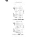
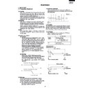
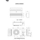
Figure 1 Temperature properties of indoor thermistors
kΩ
500k
400k
300k
200k
100k
0
-20
0
2
0
6
0
8
0
100
120
3.06k
5.78k
2.28k
1.72k
40k
30k
20k
10k
0
-20
0
2
0
6
0
40
Figure 2 Temperature properties of outdoor thermistors
Connector
CN8B
1
6
TH1 compressor thermistor
(CN8A 1 - 2 )
TH2 - TH7
Temperature (
°C)
Temperature (
°C)
Thermistor
Color
No.
Connector
Compressor thermistor
Heat exchanger pipe thermistor
Connector pin
Outdoor temp. thermistor
TH1
TH2
TH3
CN8A
CN8A
Red
No. 1 to 2
No. 3 to 4
No. 5 to 6
No. 7 to 8
No. 1 to 2
No. 3 to 4
No. 5 to 6
Orange
Suction thermistor
TH4
CN8A
Black
Thermistor unit A (suction)
TH5
CN8B
Blue
Thermistor unit B (suction)
TH6
CN8B
White
Thermistor unit C (suction)
TH7
CN8B
Brown
CN8A
Green
Connector
CN8A
18
25
°C resistance
45 k
Ω
Resistance (
Ω)
Resistance (
Ω)
0°
C resistance
14.5 k
Ω
25
°C resistance
4.431 k
Ω
Cautions when attaching or removing the board
When oper
ating only the outdoor unit (cooling 55 Hz fix
ed mode)
T
o
mak
e
only the outdoor unit r
un in cooling mode
, and apply a v
oltage of 230
V A
C
to 1 and N on the ter
minal board and push the pump do
wn s
witch.
(SW51)
(A
v
oid oper
ating the outdoor unit alone f
or long per
iods of time
.)
To measure the resistance, first remove
the soldering as shown at right.
Room temperature
thermistor TH1 (Yellow)
25
°C resistance 10 k
Ω
Heat exchange thermistor
TH2 (Orange), TH3 (Black)
25
°C resistance 4.431 k
Ω
To measure the resistance, first remove the connector from the board.
4.17k
TH2 : Heat exchanger pipe thermistor (CN8A 3 - 4 )
TH3 : Outdoor temp. thermistor (CN8A 5 - 6 )
TH4 : Suction thermistor (CN8A 7 - 8 )
TH5 : Thermistor unit A (CN8B 1 - 2 )
TH6 : Thermistor unit B (CN8B 3 - 4 )
TH7 : Thermistor unit C (CN8B 5 - 6 )
Display

