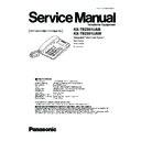
Panasonic KX-TS2351UAB / KX-TS2351UAW Service Manual ▷ View online
KX-TS2351UAB
KX-TS2351UAW
KX-TS2351UAW
Integrated Telephone System
Black Version
White Version
(for Ukraine)
Telephone Equipment
ORDER NO. KM40504668CE
1 ABOUT LEAD FREE SOLDER (PbF: Pb free)
3
1.1. Suggested PbF Solder
3
1.2. How to recognize that Pb Free solder is used
4
2 FOR SERVICE TECHNICIANS
5
3 CAUTION
5
4 BATTERY
6
4.1. Installing the Batteries
6
4.2. Battery Replacement
6
5 LOCATION OF CONTROLS
7
6 DISPLAY
8
7 SETTINGS
9
7.1. Connecting the Handset/Telephone Line Cord
9
7.2. Dialing Mode
10
7.3. Display Language
11
7.4. Dial Lock
12
7.5. How to Release the Establishment ofPassword
13
7.6. Call Restriction
14
8 OPERATIONS
15
8.1. Making Calls
15
8.2. Answering Calls
15
8.3. FLASH Button
16
8.4. Phone Book
16
9 TROUBLESHOOTING
23
10 DISASSEMBLY INSTRUCTIONS
25
11 TROUBLESHOOTING GUIDE
26
11.1. Service Hints
26
11.2. Pulse Dialing Problems
26
11.3. Tone Dialing Problems (handset)
26
11.4. No Ringing Sound When Ring Signal is Input
27
12 TEST MODE
28
13 BLOCK DIAGRAM
29
14 CIRCUIT OPERATION
30
14.1. Bell Detector Circuit
30
14.2. Line Interface
30
14.3. MODULE BLOCK DIAGRAM
30
14.4. Caller ID Detect Circuit
32
15 IC BLOCK DIAGRAM
33
15.1. IC502
33
15.2. CPU DATA (IC502)
34
15.3. RINGER IC (IC1)
35
15.4. EEPROM (IC802)
35
16 HOW TO REPLACE THE FLAT PACKAGE IC
36
16.1. PREPARATION
36
16.2. FLAT PACKAGE IC REMOVAL PROCEDURE
36
16.3. FLAT PACKAGE IC INSTALLATION PROCEDURE
37
16.4. BRIDGE MODIFICATION PROCEDURE
37
17 TERMINAL GUIDE OF THE ICs, TRANSISTORS AND DIODES
38
18 CABINET AND ELECTRICAL PARTS
39
19 ACCESSORIES AND PACKING MATERIALS
40
20 REPLACEMENT PARTS LIST
41
20.1. Base Unit
41
20.2. Accessories and Packing Materials
43
21 FOR SCHEMATIC DIAGRAM
45
22 SCHEMATIC DIAGRAM
46
22.1. Memo
48
23 CIRCUIT BOARD
49
23.1. Component View
49
23.2. Flow Solder Side View
50
Note:
Because CONTENTS 4 to 9 are the extracts from the Operating Instructions of this model, they are subject to change without
notice. Please refer to the original Operating Instructions for further information.
notice. Please refer to the original Operating Instructions for further information.
CONTENTS
Page
Page
2
KX-TS2351UAB / KX-TS2351UAW
1 ABOUT LEAD FREE SOLDER (PbF: Pb free)
Note:
In the information below, Pb, the symbol for lead in the periodic table of elements, will refer to standard solder or solder that
contains lead.
contains lead.
We will use PbF solder when discussing the lead free solder used in our manufacturing process which is made from Tin (Sn),
Silver (Ag), and Copper (Cu).
Silver (Ag), and Copper (Cu).
This model, and others like it, manufactured using lead free solder will have PbF stamped on the PCB. For service and repair
work we suggest using the same type ofsolder although, with some precautions, standard Pb solder can also be used.
work we suggest using the same type ofsolder although, with some precautions, standard Pb solder can also be used.
Caution
•
•
•
• PbF solder has a melting point that is 50°F ~70°F (30°C ~ 40°C) higher than Pb solder. Please use a soldering iron with
temperature control and adjust it to 700°F ± 20°F (370°C ± 10°C). In case ofusing high temperature soldering iron, please
be careful not to heat too long.
be careful not to heat too long.
•
•
•
• PbF solder will tend to splash ifit is heated much higher than its melting point, approximately 1100°F (600°C).
•
•
•
• Ifyou must use Pb solder on a PCB manufactured using PbF solder, remove as much ofthe original PbF solder as possible
and be sure that any remaining is melted prior to applying the Pb solder.
•
•
•
• When applying PbF solder to double layered boards, please check the component side for excess which may flow onto the
opposite side (See the figure below).
1.1.
Suggested PbF Solder
There are several types ofPbF solder available commercially. While this product is manufactured using Tin, Silver, and Copper
(Sn+Ag+Cu), you can also use Tin and Copper (Sn+Cu) or Tin, Zinc, and Bismuth (Sn+Zn+Bi). Please check the
manufacturer’s specific instructions for the melting points of their products and any precautions for using their product with other
materials.
(Sn+Ag+Cu), you can also use Tin and Copper (Sn+Cu) or Tin, Zinc, and Bismuth (Sn+Zn+Bi). Please check the
manufacturer’s specific instructions for the melting points of their products and any precautions for using their product with other
materials.
The following lead free (PbF) solder wire sizes are recommended for service of this product: 0.3mm, 0.6mm and 1.0mm.
3
KX-TS2351UAB / KX-TS2351UAW
1.2.
How to recognize that Pb Free solder is used
J019
J018
J003
JJ401
RED BLACK
GREEN
D103
D303
J015
J012
J011
J007
J017
J016
Q102
J008
R1
A
Q104
D104
C820
C102 C101
TIP RING
YELLOW GREEN
C501
C502
R161
D302
C302
C107
IC1
SW1
C111
C304
Q108
C5
C6
C202
J002
C409
C420
C106
R114
J010
J005
J006
T1
J014
3
1
D102
J009
C2
L1
C1
J101
J013
L102
L101
R126
R106
C814
C819
X801
POS101
SA101
JJ101
PC1
1
4
5
8
SW101
J3
J1
PbF
PQUP11333Z
J2
J4
C410
VR401
Q103
Q106
J001
J004
VR402
VR481
YELLO
W
Marked
(Component View)
#
9
6
3
D601
C810
R815
R815
R928
D605
TP5
TP4
TP407
TP408
Q802
R127
D600
BA
TTP
D604
DO
WN
RIGHT
ENTER
LEFT
CLEAR
1
4
8
5
IC802
C815
C555
C811
FUNCTION
A
TP7
TP404
TP405
TP8
TP6
R304
R302
R814
R520
D556
C504
C503
C115
R107
R104
R561
R563
R562
R915
Q6
R401
R403
R303
R301
R404
C431
C426 C425 C424
C483
C422
C421
C404
C481
C482
C401
C402
C205
C423
C427
C305
C105
C408
C110
Q407
Q408
Q402
Q911
Q201
Q401
Q403
Q404
Q422
Q481
Q421
C405
C406
C407
C554
R406
R422
C403
R417
JP101
R483
R408
Q406
R407
R487
R486
R405
R431
R410
R412
R413
R414
R411
R415
R416
R426
R427
R484
R485
R420
R421
R113
R206
R917
R120
TP9
TP3
TP1
C116
C103
C813
C512
C513
Q5
Q1
Q2
R205
R121
R122
R123
R201
R512
C104
R922
C203
R203
R204
R552
R551
R565
C816
C809
C807
C808
R564
R481
R553
R554
R482
R423
R424
R425
R402
R409
R428
R208
R207
R202
R504
R509
R511
R507
R503
C510
C506
C505
D501
IC501
Q501
R508
R510
R506
R505
R513
R514
R515
R516
D504
D503
D502
D202
D106
D301
D203
R117
R112
R109
R110
JP005
C201
Q107
Q502
IC302
IC301
IC201
R119
R115
R116
R118
R111
R501
R502
R9
R15
R918
R14
R13
R103
TP101
TP102
TP2
~
~
D101
Q105
Q111
Q110
D915
R916
R105
R108
R2
C3
R5
R7
R6
R8
C557
C204
C511
C556
C507
C508
C509
R923
R807
R813
Q801
R812
C806
C818
C812
Q912
C817
R811
IC803
R924
JP003
JP004
D552
D551
D554
D553
JP002
R10
R810
R921
R808
D603
D602
REDIAL
AO
H
P
A
USE/
FLASH
DIAL_LOCK
97
64
128
C822
UP
Q803
C805
33
32
LCD1
IC502
1
96
65
8
0
5
2
7
4
1
TIP
BLA
CK
1
4
8
5
8
1
RED
RING
PbF
PQ
UP11333Z
C432
C108
C301
C303
R432
TP406
TP401
BA
TTM
TP403
TP402
MIC+
MIC-
SP+
SP-
Marked
(Flow Solder Side View)
Note:
The location ofthe “PbF” marks is subject to change without notice.
4
KX-TS2351UAB / KX-TS2351UAW


