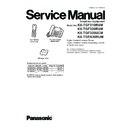
Panasonic KX-TGF310RUM / KX-TGF320RUM / KX-TGF320UCM / KX-TGFA30RUM Service Manual ▷ View online
105
KX-TGF310RUM/KX-TGF320RUM/KX-TGF320UCM/KX-TGFA30RUM
14.7. Circuit Board (Handset_BBIC Module)
14.7.1. Component View
KX-TGFA30RU CIRCUIT BOARD (Handset_BBIC Module (Component View))
C20
C 2 1
C22
C 2 4
C25
C 2 6
C 2 9
C 3 0
C 3 2
C 3 3
C34
C 3 6
C37
RTCK
C 3 8
C 3 9
3 . 0 V
C 4 0
C 4 1
C 4 3
C44
C 4 5
C 4 6
G N D _ J
C51
C 5 2
C 5 3
C 6 8
C 6 9
A T S T N
A T S T P
RA1
C 8 0 0
R A 4
RA5
C 8 0 2
C 8 0 3
C 8 0 6
C807
C808
C809
C80
C88 C 8 9
V B G / C H G M O N
C 9 6
C 9 7 C 9 8
C 9 9
C2
C3
T C K
T D I
T D O
L3
IC3
T M S
R21
R22
R23
R 2 4
R 2 5
R26
R27
R 2 8
R 3 1
R32
R 3 3
C K M / S T M
R 8 0
L801
X1
C 1 1
C12
C 1 3
C14
C15
C16
C17
C18
C 3 1
I C 1
REF-2
PNLB2414Z*
B
PbF
106
KX-TGF310RUM/KX-TGF320RUM/KX-TGF320UCM/KX-TGFA30RUM
15 Exploded View and Replacement Parts List
15.1. Cabinet and Electrical Parts (Base Unit)
15.1.1. KX-TGF310/320
Note:
(*6)(*7)This SPACER is cut from the excess parts of CUSHION/LCD (No.24).
(*6)
(*7)
(*6)
CUSHION/LCD (No.24)
(*7)
Stick 2pcs (2places)
9
11
13
7
6
5
4
14
15
17
16
18
A
19
20
23
21
21
A
35
34
33
32
31
30
29
28
27
27
28
26
25
10
12
A
A
A
22
E1
Ref.No.
Figure
A
2.6 x 8mm
PCB5
PCB4
PCB1
PCB2
PCB3
1
3
2
8
107
KX-TGF310RUM/KX-TGF320RUM/KX-TGF320UCM/KX-TGFA30RUM
15.2. Cabinet and Electrical Parts (Handset)
Note:
(*1) This cable is fixed by heat-sealing. Refer to How to Replace the Handset LCD (P.59).
(*2) The rechargeable Ni-MH Panasonic Battery is available through sales route of Panasonic.
(*3) Attach the SPACER (No. 115) to the exact location described above.
(*4)(*5)This SPACER is cut from the excess parts of CUSHION/LCD (No.105).
(*2) The rechargeable Ni-MH Panasonic Battery is available through sales route of Panasonic.
(*3) Attach the SPACER (No. 115) to the exact location described above.
(*4)(*5)This SPACER is cut from the excess parts of CUSHION/LCD (No.105).
Ref.No.
2
8 mm
B
Figure
CUSHION RUBBER
*STICK IT WITHIN THE FRAMEWORK ON P.C.B.
MIC100
107
108
109
112
113
114
E101 (*1)
E102
E103
E104
E105
E106
E107
ZA1
Spacer (
No.115
)
Battery cover
Put it in the center.
Stick it between
ribs.
ribs.
CUSHION/LCD (No.105)
(*5)
(*5)
(*4)
(*4)
101
102
103
104
105
106
110
111
115 (*3)
116
(*2)
117
B
PCB100
B
108
KX-TGF310RUM/KX-TGF320RUM/KX-TGF320UCM/KX-TGFA30RUM
15.3. Cabinet and Electrical Parts (Charger Unit)
200-1
200-2
200-3
200-4
200-5
200
Click on the first or last page to see other KX-TGF310RUM / KX-TGF320RUM / KX-TGF320UCM / KX-TGFA30RUM service manuals if exist.

