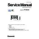
Panasonic PT-RQ13K Service Manual ▷ View online
3
PREFACE
< RQ13K >
There are special components used in this equipment which are important for safety. These parts are marked by 7 in the schematic
diagram, circuit board diagrams, exploded views and replacement parts list. It is essential that these critical parts should be replaced
with manufacturer’s specified parts to prevent shock, fire, or other hazards. Do not modify the original design without permission of
manufacturer.
IMPORTANT SAFETY NOTICE
WARNING:
This equipment has been tested and found to comply with the limits for a Class A digital device, pursuant to part 15 of the FCC Rules.
These limits are designed to provide reasonable protection against harmful interference when the equipment is operated in a
commercial environment.
This equipment generates, uses, and can radiate radio frequency energy and, if not installed and used in accordance with the
instruction manual, may cause harmful interference to radio communications.
Operation of this equipment in a residential area is likely to cause harmful interference in which case the user will be required to
correct the interference at his own expense.
CAUTION:
Any unauthorized changes or modifications to this equipment will void the user’s authority to operate this device.
Cautions when transporting
f
Before using the projector, remove the dust sponge from the mounting portion of the projection lens and store it
for the future use. When transporting the projector, remove the projection lens before attaching the dust sponge.
Otherwise dust will accumulate inside and may cause malfunctions.
f
Transport the projector with 2 or more people. Failure to do so may drop the projector, which may result in
damage or deformation of the projector, or injury.
f
When transporting the projector, hold it securely by its bottom and avoid excessive vibration and impacts. They
may damage the internal components and result in malfunctions.
f
Do not transport the projector with the adjustable feet extended. Doing so may damage the adjustable feet.
Cautions when installing
r
Do not set up the projector outdoors.
The projector is designed for indoor use only.
r
Do not set up the projector in the following locations.
f
Places where vibration and impacts occur such as in a car or vehicle: Doing so may cause damage to internal
components or malfunction.
f
Location close to sea or where corrosive gas may occur: The projector may fall due to corrosion. Also, failure to
do so may shorten the life of the components and result in malfunctions.
f
cases due to the heated air from the air exhaust port or the hot or cooled air. Make sure that the exhaust
from the projector or other equipment, or the air from the air conditioner does not blow toward the front of the
projector.
f
the light source, or result in deformation of the projector due to heat, which may cause malfunctions.
Follow the operating environment temperature of the projector.
Follow the operating environment temperature of the projector.
f
Near high-voltage power lines or near motors: Doing so may interfere with the operation of the projector.
f
Places where there is high-power laser equipment: Directing a laser beam onto the projection lens surface
causes damage to the DLP chips.
r
Be sure to ask a specialized technician or your dealer when installing the projector on
a ceiling.
The optional Ceiling Mount Bracket is required.
Model No.: ET-PKD520H (for High Ceilings), ET-PKD520S (for Low Ceilings), ET-PKD520B (Projector Mount
Model No.: ET-PKD520H (for High Ceilings), ET-PKD520S (for Low Ceilings), ET-PKD520B (Projector Mount
Bracket)
r
AL LINK
connection.
Image and sound may be disrupted if cable transmission characteristics cannot be obtained due to inadequate
installation.
4
PREFACE
< RQ13K >
r
Do not install the projector at an altitude of 4 200 m (13 780') or higher above sea level.
r
Do not use the projector in a location that the ambient temperature exceeds 45 °C
(113 °F).
Using the projector in a location that the altitude is too high or the ambient temperature is too high may reduce the
life of the components or result in malfunctions.
The upper limit of the operating environment temperature differs depending on the altitude or the [OPERATING
The upper limit of the operating environment temperature differs depending on the altitude or the [OPERATING
MODE] setting in the [PROJECTOR SETUP] menu → [OPERATION SETTING]
Altitude above sea level
Setting for [OPERATING MODE]
[NORMAL], [USER1], [USER2], [USER3]
[ECO], [LONG LIFE1], [LONG LIFE2],
[LONG LIFE3]
Altitude of 0 m (0') or higher
to lower than 1 400 m
(4 593')
0 °C (32 °F) to 45 °C (113 °F)
0 °C (32 °F) to 40 °C (104 °F)
Altitude of 1 400 m (4 593')
or higher to lower than
2 700 m (8 858')
0 °C (32 °F) to 40 °C (104 °F)
Altitude of 2 700 m (8 858')
or higher to lower than
4 200 m (13 780')
The projector cannot be used.
When the Smoke Cut Filter is used, the operating environment temperature should be between 0 °C (32 °F) and
35 °C (95 °F) regardless of the [OPERATING MODE] setting. It cannot be used at an altitude of 1 400 m (4 593')
or higher above sea level.
r
Projection in all 360° direction is possible.
360°
360°
360°
360° vertically
360° horizontally
360° tilted
(combination of vertical and horizontal)
r
Cautions when setting up the projector
f
purposes may damage the projector.
f
The adjustable feet can be removed if not needed in the installation. However, do not use the screw holes
holes of the adjustable feet. Failure to do so may cause damage to the projector.
r
The projector may not work properly due to strong radio wave from the broadcast
station or the radio.
If there is any facility or equipment which outputs strong radio waves near the installation location, install the
, wrap the LAN cable connected to the
<DIGITAL LINK/LAN> terminal using a piece of metal foil or a metal pipe which is grounded at both ends.
r
Focus adjustment
The high clarity projection lens is thermally affected by the light from the light source, making the focus unstable in
the period just after switching on the power. It is recommended that images be projected continuously for at least
30 minutes before the focus is adjusted.
5
PREFACE
< RQ13K >
Table of Contents
1. Safety Precautions
2. Specifications
2. Specifications
SECTION 1 SERVICE INFORMATION
1. The name of each part
2. Menu Navigation
3. Service Mode
4. Notes on service
5. Troubleshooting
2. Menu Navigation
3. Service Mode
4. Notes on service
5. Troubleshooting
SECTION 2 DISASSEMBLY PROCEDURES
1. Parts Locations
2. Disassembly Instructions
2. Disassembly Instructions
SECTION 3 ADJUSTMENTS
1. Adjustment item and a procedure
2. Software Update Procedure
2. Software Update Procedure
SECTION 4 SCHEMATIC DIAGRAM
1. Block Diagram
2. Interconnection Block Diagram
3. Schematic Diagram
4. Circuit Boards Diagram
2. Interconnection Block Diagram
3. Schematic Diagram
4. Circuit Boards Diagram
[ Note ]
* For replacement parts and exploded view, refer to the separated manual "PARTS LIST".
6
PREFACE
< RQ13K >
1. Safety Precautions
1.1. General Guidelines
- For continued safety, no modification of any circuit must be attempted.
- Unplug the power cord from the power outlet before disassembling this projector.
- Use correctly the supplied power cord and must ground it.
- It is advisable to use an isolation transformer in the AC power line before the service.
- Be careful not to touch the rotation part (cooling fan, etc.) of this projector when you service with the upper case removed
and the power supply turned ON.
- Observe the original lead dress during the service. If a short circuit is found, replace all the parts overheated or damaged
by the short circuit.
- After the service, all the protective devices such as insulation barriers, insulation papers, shields, and isolation R-C combi-
nations must be properly installed.
- After the service, check the leakage current to prevent the customer from getting an electric shock.
1.2. Leakage Current Check
1. Prepare the measuring circuit as shown in Fig.1.
Be sure to use a voltmeter having the performance described in Table 1.
2. Assemble the circuit as shown in Fig. 2. Plug the power cord in a power outlet.
3. Connect M1 to T1 according to Fig. 2 and measure the voltage.
4. Change the connection of M1 from T1 to T2 and measure the voltage again.
5. The voltmeter must read 0.375 V or lower in both of steps 3 and 4. This means that the current must be 0.75mA or less.
6. If the reading is out of the above standard, the projector must be repaired and rechecked before returning to the customer
because of a possibility of an electric shock.
M1
M2
Rs
Cs
Rb
10KΩ ±0.1%
0.022µF
±1.0%
Vb
(V) V
Rs: 1500 Ω±0.1%
Cs: 0.22 µF±1.0%
Rb: 500 Ω±0.1%
to T1
or T2
in FIg.2
Weighted leakage current=Vb / 500 (A)
Fig. 1
Isolation transformer
T1
T2
connection
to power outlet
M1
M2
Fig.2
Projector
Measuring
Circuit (Fig.1)
Performance
Voltmeter
(rms reading)
Accurancy:
≤ 2%
Input resistance:
≥ 1 MΩ
Input capacitance: ≤ 200 pF
Frequency range: 15 Hz to 1 MHz
Table. 2


