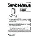
Panasonic KX-NCV200BX / KX-TVM204X / KX-TVM296X (serv.man3) Service Manual ▷ View online
ORDER NO. KMS0611298CE
ACD Report Server
KX-NCV200BX
KX-TVM204X
KX-TVM296X
KX-TVM204X
KX-TVM296X
(for Asia, Middle Near East, Latin America and Africa)
2
KX-NCV200BX / KX-TVM204X / KX-TVM296X
TABLE OF CONTENTS
PAGE
PAGE
1 Safety Precautions -----------------------------------------------3
1.1. For Service Technicians ---------------------------------3
1.2. Insulation Resistance Test -------------------------------3
1.2. Insulation Resistance Test -------------------------------3
2 Warning --------------------------------------------------------------4
2.1. Caution--------------------------------------------------------4
2.2. About Lead Free Solder (PbF: Pb free) --------------5
2.2. About Lead Free Solder (PbF: Pb free) --------------5
3 Specifications ------------------------------------------------------6
3.1. Over View ----------------------------------------------------7
3.2. Client Application-------------------------------------------9
3.3. LAN Features -----------------------------------------------9
3.2. Client Application-------------------------------------------9
3.3. LAN Features -----------------------------------------------9
4 Technical Descriptions---------------------------------------- 10
4.1. Functional Block Diagram------------------------------ 10
4.2. Main Board------------------------------------------------- 11
4.3. Voice Buffer SRAM -------------------------------------- 20
4.4. Utility--------------------------------------------------------- 31
4.2. Main Board------------------------------------------------- 11
4.3. Voice Buffer SRAM -------------------------------------- 20
4.4. Utility--------------------------------------------------------- 31
5 Location of Controls and Components------------------ 41
5.1. Names and Locations----------------------------------- 41
6 Installation Instructions--------------------------------------- 42
6.1. System Connection Diagram-------------------------- 42
6.2. Connection Examples----------------------------------- 43
6.3. Connecting the AC Adaptor --------------------------- 44
6.4. PBX Connections ---------------------------------------- 45
6.5. System Componets-------------------------------------- 51
6.6. Installation-------------------------------------------------- 52
7 Troubleshooting Guide---------------------------------------- 54
7.1. The RUN LED Does Not Light or is Abnormal
when the Power Switch is Turned On -------------- 54
7.2. The RUN LED Does Not Light when DPT is
Connected ------------------------------------------------- 55
7.3. TVM204X DSP Card is Out of Order---------------- 56
7.4. USB Interfaceis is Out of Order ---------------------- 57
7.5. LAN Interface is Out of Order ------------------------- 57
7.6. Modem Card is Out of Order -------------------------- 58
7.7. Main Card is Out of Order ----------------------------- 59
7.4. USB Interfaceis is Out of Order ---------------------- 57
7.5. LAN Interface is Out of Order ------------------------- 57
7.6. Modem Card is Out of Order -------------------------- 58
7.7. Main Card is Out of Order ----------------------------- 59
8 Service Fixture & Tools --------------------------------------- 60
9 Disassembly and Assembly Instructions--------------- 61
9 Disassembly and Assembly Instructions--------------- 61
9.1. How to Remove the Cable Cover -------------------- 61
9.2. How to Remove the Front Cover--------------------- 61
9.3. How to Remove the Hard Disk Drive Unit and
9.2. How to Remove the Front Cover--------------------- 61
9.3. How to Remove the Hard Disk Drive Unit and
PCB1 -------------------------------------------------------- 62
10 Miscellaneous ---------------------------------------------------- 64
10.1. Terminal Guide of the ICs Transistors and
Diodes------------------------------------------------------- 64
10.2. How To Replace a Flat Package IC ----------------- 65
11 Schematic Diagram--------------------------------------------- 66
11.1. Functional Block Diagram------------------------------ 66
11.2. Main No.1 CPU, ASIC and Memory Block
11.2. Main No.1 CPU, ASIC and Memory Block
Diagram----------------------------------------------------- 67
11.3. Main No.2 SLOT, HDD and Interface Block
Diagram----------------------------------------------------- 68
11.4. Main No.3 LAN and USB Block Diagram ---------- 69
11.5. Main No.4 Power Block Diagram -------------------- 70
11.6. Memo-------------------------------------------------------- 71
11.7. Main No1 CPU, ASIC and Memory------------------ 72
11.8. Main No.2 SLOT, HDD and Modem Interface ---- 76
11.9. Main No.3 LAN and USB------------------------------- 80
11.10. Main No.4 Power ----------------------------------------- 84
11.11. LED ---------------------------------------------------------- 88
11.12. Memo ------------------------------------------------------- 89
12 Printed Circuit Board------------------------------------------ 90
12.1. Main Board (Component View) ---------------------- 90
12.2. Main Board (Bottom View) ---------------------------- 91
12.3. LED Board------------------------------------------------- 92
12.2. Main Board (Bottom View) ---------------------------- 91
12.3. LED Board------------------------------------------------- 92
13 Appendix Information of Schematic Diagram -------- 92
14 Exploded View and Replacement Parts List----------- 93
14 Exploded View and Replacement Parts List----------- 93
14.1. Cabinet and Electrical Parts Location -------------- 93
14.2. Accessories and Packing Material ------------------ 94
14.3. Replacement Parts List -------------------------------- 95
14.2. Accessories and Packing Material ------------------ 94
14.3. Replacement Parts List -------------------------------- 95
15 KX-TVM204X (4-Port Digital Expansion Card) -------106
15.1. Specifications (KX-TVM204X)-----------------------107
15.2. Technical Descriptions (KX-TVM204X) -----------107
15.3. Installation Instructions (KX-TVM204X)-----------120
15.4. Miscellaneous (KX-TVM204X) ----------------------122
15.5. Appendix Information of Schematic Diagram
15.2. Technical Descriptions (KX-TVM204X) -----------107
15.3. Installation Instructions (KX-TVM204X)-----------120
15.4. Miscellaneous (KX-TVM204X) ----------------------122
15.5. Appendix Information of Schematic Diagram
(KX-TVM204X) ------------------------------------------123
15.6. Printed Circuit Board (KX-TVM204X) -------------132
15.7. Exploded View and Replacement Parts List
15.7. Exploded View and Replacement Parts List
(KX-TVM204X) ------------------------------------------136
16 KX-TVM296X (Modem Card) ------------------------------- 143
16.1. Specifications (KX-TVM296X)-----------------------144
16.2. Installation Instructions (KX-TVM296X)-----------145
16.3. Miscellaneous (KX-TVM296X) ----------------------146
16.4. Appendix Information of Schematic Diagram
16.2. Installation Instructions (KX-TVM296X)-----------145
16.3. Miscellaneous (KX-TVM296X) ----------------------146
16.4. Appendix Information of Schematic Diagram
(KX-TVM296X) ------------------------------------------147
16.5. Printed Circuit (KX-TVM296X) ----------------------150
16.6. Exploded View and Replacement Parts List
16.6. Exploded View and Replacement Parts List
(KX-TVM296X) ------------------------------------------151
3
KX-NCV200BX / KX-TVM204X / KX-TVM296X
1 Safety Precautions
1. Before servicing, unplug the power cord to prevent an electric shock.
2. When replacing parts, use only the manufacturer's recommended components for safety.
3. Check the condition of the power cord. Replace if wear or damage is evident.
4. After servicing, be sure to restore the lead dress, insulation barriers, insulation papers, shields, etc.
5. Before returning the serviced equipment to the customer, be sure to perform the following insulation resistance test to prevent
the customer from being exposed to shock hazards.
1.1.
For Service Technicians
ICs and LSIs are vulnerable to static electricity.
When repairing, the following precautions will help prevent recurring malfunctions.
When repairing, the following precautions will help prevent recurring malfunctions.
1. Cover the plastic parts boxes with aluminum foil.
2. Ground the soldering irons.
3. Use a conductive mat on the worktable.
4. Do not touch IC or LSI pins with bare fingers.
2. Ground the soldering irons.
3. Use a conductive mat on the worktable.
4. Do not touch IC or LSI pins with bare fingers.
1.2.
Insulation Resistance Test
1. Unplug the power cord and short the two prongs of the plug with a jumper wire.
2. Turn on the power switch.
3. Measure the resistance value with ohmmeter between the jumpered AC plug and each exposed metal cabinet part, such as
2. Turn on the power switch.
3. Measure the resistance value with ohmmeter between the jumpered AC plug and each exposed metal cabinet part, such as
screw threads, control shafts, handle brackets, etc.
Note:
Note:
Some exposed parts may be isolated from the chassis by design. These will read infinity.
4. If the measurement is outside the specified limits, there is a possibility of shock hazard. The equipment should be repaired
and rechecked before it is returned to the customer.
4
KX-NCV200BX / KX-TVM204X / KX-TVM296X
2 Warning
Guidelines for handling HDD
1. HDD must be handled standing on rubber insulating.
2. Operator must wear grounding strap at when handling HDD.
3. Do not touch circuit.
4. Metal frame and HDD must be assembled with shock-proofed torque controlled screwdriver. (Loosing torque 0.4~0.6n. m)
5. Do not press HDD when securing screw. (Hold metal frame)
6. Take care when handling HDD. HDD is sensitive to shock.
2.1.
Caution
The power socket wall outlet should be located near this equipment and be easily accessible.

