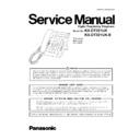
Panasonic KX-DT321UA Service Manual ▷ View online
4
KX-DT321UA/KX-DT321UA-B
2.2.
Discarding of P. C. Board
When discarding P. C. Board, delete all personal information such as telephone directory and caller list or scrap P. C. Board.
3 Specifications
3.1.
General Descriptions
Design and specifications are subject to change without notice.
Station Loop Limit:
90 ohms
Calling Method:
2 pair wire
Jacks:
Handset Jack, TEL Jack (PBX and DXDP),Headset Jack
Dimensions:
Low Angle:
High Angle:
High Angle:
210 (D)mm
× 175 (W)mm × 129 (H)mm
188 (D)mm
× 175 (W)mm × 148 (H)mm
Weight:
Under 800 g
5
KX-DT321UA/KX-DT321UA-B
4 Technical Descriptions
4.1.
Block Diagram
TE
L
-J
a
c
k
DX
DP
-J
ac
k
JK
2
AS
IC
IC2
Han
d
s
e
t
Ja
c
k
LC
D
EEP
R
O
M
IC5
JK
1
Q1
PD
X
0
PD
X
1
PD
R
D
a
ta
C
o
muni
ca
ti
o
n
T1
Q3
DDX
0
DDX
1
DDR
Q6
Q5
D
a
ta
C
o
muni
ca
ti
on
Po
w
e
r
IC5
L5
D3
.3
V
A3
.3
V
OS
R
OS
X
OE
P
0
OC
K
DX
DR
BC
L
K
FS
L
E
D
1
13
Q
31 Q
3
5
N
R
O
W
0 7
CL
M
0
5
Ke
y
S
W
1 35
Hook
SW
JK
3
Re
se
t
IC7
S
p
ea
k
e
r
Ph
o
n
e
IC3
3.
3V
5.
0V
IC
8
,D
6
3
CO
D
E
C
IC4
CP
U
IC6
Ton
e
D
B
0 7
A
D
R
0
5
W
E
N,
R
E
N,
IN
T
N
SC
K,
D
A
T
A
LC
D_
S
C
LK
LC
D_
S
T
B
LC
D_
DA
T
A
SC
L
,SD
A
X1
He
ad
s
e
t
Ja
c
k
JK
4
Re
se
t
IC7
SW
IC9
Am
p
IC11
LC
D_
C
N
T
1
LC
D_
C
N
T
2
L
o
gic
IC10
T2
KX-DT321
UA
/KX-DT321
UA
-B Bloc
k Dia
g
ra
m
6
KX-DT321UA/KX-DT321UA-B
4.2.
Circuit Operations
4.2.1.
Key Input Control Curcuit
The key data is under the matrix control by 20 to 23(KEYOUT) and 28 to 35(KEYIN) of IC6.
The key information output from KEYOUT is input into KEYIN, when the key is pressed.
The key information output from KEYOUT is input into KEYIN, when the key is pressed.
7
KX-DT321UA/KX-DT321UA-B
4.2.2.
LCD Control Circuit
KX-DT321 uses a 16 characters by 1 line LCD.
Power is supplied to LCD from +5V rail, formed as follows:
Pin 24 of IC6 is made to switch, forming a square waveform which is input to IC8 pin 2. The output of IC8 pin 4 switches between
+3.3V and 0V. When the output is low, C603 charges via D61. When output is high, anode of D62 rises to 6V and C601 is charged
via D62. D63 limits the voltage across C601 to +5V. D5V powers the LCD and also IC10.
IC10 is a converter circuit to allow the 3V output of IC6 to drive the LCD, which uses 5V inputs.
LCD contrast is adjusted by means of voltage level supplied at pin 3 of LCD module.
It is adjusted to one of 3 settings by means of a bias circuit (R600, R622) and IC6 pins 19 and 59, according to the following table:
It is adjusted to one of 3 settings by means of a bias circuit (R600, R622) and IC6 pins 19 and 59, according to the following table:
Data is sent to the LCD module via IC10 from the processor using a 3-wire interface (IC6 pins 13, 14, 15).
Contrast
IC6 pin 59
IC6 pin 19
High
L
L
Middle Z
L
Low
Z
L


