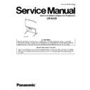
Panasonic UB-8325 Service Manual ▷ View online
Order No. KM70512065CE
H19
Electronic Board (Interactive Panaboard)
UB-8325
2
UB-8325
TABLE OF CONTENTS
PAGE
PAGE
1 General Precaution -----------------------------------------------4
1.1. Safety Precaution ------------------------------------------4
1.2. Electrical Test -----------------------------------------------4
1.3. For Service Technician------------------------------------5
1.4. About Lead Free Solder (PbF: Pb free) --------------5
1.2. Electrical Test -----------------------------------------------4
1.3. For Service Technician------------------------------------5
1.4. About Lead Free Solder (PbF: Pb free) --------------5
2 Introduction ---------------------------------------------------------6
2.1. Before using this manual ---------------------------------6
2.2. Specification -------------------------------------------------7
2.3. Options, Accessories and Supplies -------------------8
2.4. External View------------------------------------------------9
2.5. Control Panel, Electronic Pen and Electronic
2.2. Specification -------------------------------------------------7
2.3. Options, Accessories and Supplies -------------------8
2.4. External View------------------------------------------------9
2.5. Control Panel, Electronic Pen and Electronic
Eraser Operations---------------------------------------- 10
2.6. Exterior Dimensions ------------------------------------- 12
2.7. Main Components Location & PCB, Switches
2.7. Main Components Location & PCB, Switches
and Sensors Identification ----------------------------- 13
3 Installation Instructions--------------------------------------- 15
3.1. Installation Requirements ------------------------------ 15
3.2. Minimum Space Requirements ----------------------- 15
3.3. Assembling the Panaboard ---------------------------- 16
3.4. Repacking-------------------------------------------------- 20
3.5. Assembling the Optional Stand (KX-BP065) ------ 21
3.6. Setting the Optional Wall-mounting Kit (KX-
3.2. Minimum Space Requirements ----------------------- 15
3.3. Assembling the Panaboard ---------------------------- 16
3.4. Repacking-------------------------------------------------- 20
3.5. Assembling the Optional Stand (KX-BP065) ------ 21
3.6. Setting the Optional Wall-mounting Kit (KX-
B063) -------------------------------------------------------- 24
4 Mechanical Function------------------------------------------- 27
4.1. Screen Feed Mechanism ------------------------------ 27
4.2. Electronic Pen (or Electronic Eraser) Position
4.2. Electronic Pen (or Electronic Eraser) Position
Detection Mechanism ----------------------------------- 28
4.3. Scanning Mechanism ----------------------------------- 29
4.4. Printer Mechanism --------------------------------------- 30
4.4. Printer Mechanism --------------------------------------- 30
5 Troubleshooting Guide---------------------------------------- 35
5.1. Error Code ------------------------------------------------- 35
5.2. Image Data Problem ------------------------------------ 40
5.3. Drawing (Erasing) Problem with Electronic
5.2. Image Data Problem ------------------------------------ 40
5.3. Drawing (Erasing) Problem with Electronic
Pen and Electronic Eraser ---------------------------- 46
5.4. PC Interface Error Message on PC Screen ------- 48
5.5. Others ------------------------------------------------------- 48
5.6. Requirement after replacing, servicing and
5.5. Others ------------------------------------------------------- 48
5.6. Requirement after replacing, servicing and
handling----------------------------------------------------- 51
6 Disassembly and Assembly Instructions --------------- 52
6.1. Screen Unit ------------------------------------------------ 52
6.2. Screen Motor ---------------------------------------------- 57
6.3. Relay Board ----------------------------------------------- 58
6.4. Interactive Board ----------------------------------------- 59
6.5. LED Array and Image Sensor------------------------- 60
6.6. Printer Unit ------------------------------------------------- 62
6.7. Pen Holder ------------------------------------------------- 71
6.8. Electronic Eraser ----------------------------------------- 72
7 Test Mode---------------------------------------------------------- 73
7.1. Test Mode Menu------------------------------------------ 73
7.2. Test Pattern ------------------------------------------------ 74
7.3. Test Mode Operation ------------------------------------ 75
7.2. Test Pattern ------------------------------------------------ 74
7.3. Test Mode Operation ------------------------------------ 75
8 Measurements and Adjustments -------------------------- 76
8.1. Image Sensor Adjustment ----------------------------- 76
8.2. Scanning Contrast Adjustment ----------------------- 83
8.3. Left and Right Receiver Level Adjustments ------- 84
8.4. Receiver Distance Adjustment------------------------ 86
8.5. Adjustment for Electronic Pen and Electronic
8.2. Scanning Contrast Adjustment ----------------------- 83
8.3. Left and Right Receiver Level Adjustments ------- 84
8.4. Receiver Distance Adjustment------------------------ 86
8.5. Adjustment for Electronic Pen and Electronic
Eraser ------------------------------------------------------- 88
9 Maintenance------------------------------------------------------ 93
9.1. Maintenance Table -------------------------------------- 93
9.2. Cleaning Screen ----------------------------------------- 93
9.3. Caring for the Eraser ----------------------------------- 93
9.4. Cleaning the Pickup Roller and Platen Roller ---- 94
9.5. Cleaning Thermal Head (Printer Head) ------------ 95
9.6. Replacing Thermal Transfer Film-------------------- 95
9.7. Replacing the eraser cloth for the Electronic
Eraser------------------------------------------------------- 96
10 Block and Connection Diagrams-------------------------- 97
10.1. Block Diagram -------------------------------------------- 97
10.2. Connection Diagram ------------------------------------ 98
10.2. Connection Diagram ------------------------------------ 98
11 Explanation of Connector ----------------------------------- 99
12 Schematic Diagram ------------------------------------------- 105
12.1. Power Board (for 100~120VAC power system
and 220~240VAC power system) ------------------ 105
12.2. Control Board -------------------------------------------- 107
12.3. Motor Driver Board ------------------------------------- 115
12.4. Panel Board ---------------------------------------------- 116
12.5. Relay Board ---------------------------------------------- 117
12.6. Sensor Board (Top, Paper, Film End and Door
12.3. Motor Driver Board ------------------------------------- 115
12.4. Panel Board ---------------------------------------------- 116
12.5. Relay Board ---------------------------------------------- 117
12.6. Sensor Board (Top, Paper, Film End and Door
Sensors) -------------------------------------------------- 118
12.7. LED Array Boards -------------------------------------- 119
12.8. Interactive Board---------------------------------------- 120
12.9. Ultrasonic Sensor, Infrared Sensor and
12.8. Interactive Board---------------------------------------- 120
12.9. Ultrasonic Sensor, Infrared Sensor and
Thermo Sensor Boards ------------------------------- 126
12.10. Electronic Pen Board ---------------------------------- 127
12.11. Electronic Eraser Board------------------------------- 128
13 Printed Circuit Board----------------------------------------- 129
13.1. Control Board -------------------------------------------- 129
13.2. Interactive Board---------------------------------------- 131
13.3. Ultrasonic Sensor Board ------------------------------ 132
13.4. Infrared Sensor Board --------------------------------- 133
13.5. Thermo Sensor Board --------------------------------- 133
13.6. Motor Driver Board ------------------------------------- 133
13.7. Panel Board ---------------------------------------------- 133
13.8. Relay Board ---------------------------------------------- 134
13.9. Top Sensor Board -------------------------------------- 134
13.10. Paper Sensor Board ----------------------------------- 134
13.11. Film End Sensor Board ------------------------------- 134
13.12. Door Sensor Board------------------------------------- 134
13.13. Power Board --------------------------------------------- 135
13.14. LED Array Boards -------------------------------------- 136
13.15. Pen Board ------------------------------------------------ 137
13.16. Eraser Board--------------------------------------------- 137
13.13. Power Board --------------------------------------------- 135
13.14. LED Array Boards -------------------------------------- 136
13.15. Pen Board ------------------------------------------------ 137
13.16. Eraser Board--------------------------------------------- 137
14 Exploded View and Replacement Parts List---------- 138
14.1. Screen Unit----------------------------------------------- 138
14.2. Optical Unit ----------------------------------------------- 140
14.3. Printer Unit ----------------------------------------------- 142
14.4. Packing Materials--------------------------------------- 145
14.5. Tool --------------------------------------------------------- 145
14.6. Electronic Pen ------------------------------------------- 146
14.7. Electronic Eraser---------------------------------------- 146
14.8. Optional Stand------------------------------------------- 147
14.9. Control Board -------------------------------------------- 148
14.10. Panel Board ---------------------------------------------- 149
14.11. Power Board --------------------------------------------- 150
14.12. Motor Driver Board ------------------------------------- 151
3
UB-8325
14.13. Top Sensor Board -------------------------------------- 151
14.14. Door Sensor Board------------------------------------- 151
14.15. Film End Sensor Board ------------------------------- 151
14.16. Paper Sensor Board ----------------------------------- 151
14.17. Interactive Board---------------------------------------- 151
14.18. Ultrasonic Sensor Board------------------------------ 153
14.19. Infrared Sensor Board--------------------------------- 153
14.20. Thermo Sensor Board--------------------------------- 153
14.21. Relay Board---------------------------------------------- 153
14.22. LED Array Board (A)----------------------------------- 153
14.23. LED Array Board (B)----------------------------------- 154
14.24. LED Array Board (C)----------------------------------- 154
14.25. Pen Board ------------------------------------------------ 154
14.26. Eraser Board--------------------------------------------- 155
14.27. Pen FPC Board ----------------------------------------- 155
14.28. Eraser FPC Board-------------------------------------- 155
4
UB-8325
1 General Precaution
1.1.
Safety Precaution
1. Before servicing, unplug the power cord to prevent electrical shock hazard.
2. When replacing parts, use only manufacture’s recommended components for safety.
3. Check the condition of power cord. Replace if wear or damage is evident.
4. After servicing, be sure to restore the lead dress, insulation barriers, insulation papers, shields, etc.
5. Before returning the serviced equipment to the customer, perform the following electrical tests to prevent shock hazard.
1.2.
Electrical Test
1. Unplug the power cord and check for continuity between the earth ground connection on the plug and the metal cabinet.
There should be zero ohm resistance found.
2. With the unit unplugged, short the AC Live-Neutral of the plug with a jumper wire.
3. Turn ON the power switch.
4. Measure the resistance value with an ohmmeter between the shorted AC plug and each exposed metal cabinet part, such as
3. Turn ON the power switch.
4. Measure the resistance value with an ohmmeter between the shorted AC plug and each exposed metal cabinet part, such as
screwhead, etc.
Note:
Note:
Some exposed parts may be isolated from the chassis by design. They read infinity.
5. If the measurement is less than 1 M
Ω
, a possibility for electric shock may exit.
Note:
This hazardous condition must be corrected before the unit is returned to the end user.

