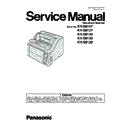
Panasonic KV-S8147 / KV-S8127 / KV-S8150 / KV-S8130 / KV-S8120 Service Manual ▷ View online
3
8.7.10. Hopper Upper Limit Sensor Board --------------68
8.7.11. ADF Door Inner Plate (Feed Unit Assy)--------68
8.7.12. Pressure Sensor -------------------------------------68
8.7.13. USS (L) Board ----------------------------------------69
8.7.14. USS (R) / Wait Sensor Board---------------------69
8.7.15. Bent Paper R Sensor Board ----------------------69
8.7.16. Bent Paper S Sensor Board ----------------------69
8.7.17. Exit Guide----------------------------------------------69
8.7.18. Stacker Position Sensor----------------------------69
8.7.19. Stacker Upper Limit Sensor Board --------------69
8.7.20. Stacker Home Sensor Board ---------------------69
8.7.21. Exit Tray Plate ----------------------------------------70
8.7.22. Stacker Motor -----------------------------------------70
8.7.23. CIS (F) Relay Board --------------------------------70
8.7.24. Upper Relay Board ----------------------------------70
8.7.25. Free Roller 1 L / R Assy----------------------------71
8.7.26. Free Roller 2 L / R Assy ---------------------------71
8.7.27. Free Roller 3 Assy -----------------------------------71
8.7.28. Free Roller 4 Assy -----------------------------------72
8.7.29. Free Roller Exit Assy -------------------------------73
8.8. Wiring--------------------------------------------------------74
8.8.1. Main Chassis Wiring --------------------------------74
8.8.2. Sub Chassis Wiring ---------------------------------76
8.8.2. Sub Chassis Wiring ---------------------------------76
8.9. Requirement After Parts Replacement--------------77
9 Maintenance-------------------------------------------------------78
9.1. Maintenance Chart ---------------------------------------78
9.2. Cleaning ----------------------------------------------------79
9.3. Replacing Limited Life Parts ---------------------------80
9.2. Cleaning ----------------------------------------------------79
9.3. Replacing Limited Life Parts ---------------------------80
10 Service Utility & Scanner Service Mode -----------------81
10.1. Main Menu Indication for Service Utility ------------81
10.2. List of Functions for Service Utility -------------------82
10.3. Operation ---------------------------------------------------84
10.2. List of Functions for Service Utility -------------------82
10.3. Operation ---------------------------------------------------84
10.3.1. Scanner Status ---------------------------------------84
10.3.2. Error Code ---------------------------------------------85
10.3.3. Error Log -----------------------------------------------87
10.3.4. Scanner Information --------------------------------87
10.3.5. Scanner Counter -------------------------------------87
10.3.6. Scanner Condition -----------------------------------88
10.3.7. Test ------------------------------------------------------90
10.3.8. Adjustment --------------------------------------------94
10.3.9. Other ----------------------------------------------------97
10.4. Scanner Service Mode ----------------------------------98
11 Troubleshooting ----------------------------------------------- 100
11.1. Troubleshooting-1 (with no error message on
PC) --------------------------------------------------------- 100
11.2. Troubleshooting-2 (with an error message on
PC) --------------------------------------------------------- 102
12 Block Diagram-------------------------------------------------- 115
12.1. Block Diagram-1 (Image processing)-------------- 115
12.2. Block Diagram -2 (Board) ---------------------------- 116
12.3. Explanation of Connector----------------------------- 117
12.2. Block Diagram -2 (Board) ---------------------------- 116
12.3. Explanation of Connector----------------------------- 117
13 Schematic Diagram ------------------------------------------- 132
13.1. Drive Board ---------------------------------------------- 133
13.2. Control Board-------------------------------------------- 142
13.3. RELAY Board ------------------------------------------- 155
13.2. Control Board-------------------------------------------- 142
13.3. RELAY Board ------------------------------------------- 155
13.3.1. UPPER RELAY Board ---------------------------- 155
13.3.2. LOWER RELAY Board --------------------------- 158
13.3.3. CIS (F) RELAY Board----------------------------- 160
13.3.4. CIS (B) RELAY Board ---------------------------- 161
13.3.5. PANEL Board --------------------------------------- 162
13.3.2. LOWER RELAY Board --------------------------- 158
13.3.3. CIS (F) RELAY Board----------------------------- 160
13.3.4. CIS (B) RELAY Board ---------------------------- 161
13.3.5. PANEL Board --------------------------------------- 162
13.4. LCD Board ----------------------------------------------- 163
13.5. SENSOR Board ---------------------------------------- 164
13.5.1. BENT PAPER R SENSOR Board ------------- 164
13.5.2. BENT PAPER S SENSOR Board ------------- 166
13.5.3. DFP HOME SENSOR Board ------------------- 168
13.5.4. EXIT SENSOR Board ---------------------------- 169
13.5.5. PAPER SENSOR RELAY Board -------------- 170
13.5.6. HOPPER HOME SENSOR Board ------------ 171
13.5.7. HOPPER UPPER LIMIT SENSOR Board -- 172
13.5.8. PAPER PATH SELECT Board ----------------- 173
13.5.9. PLATEN HOME SENSOR Board ------------- 174
13.5.10. POST-LMPRINTER DOOR SENSOR
Board ------------------------------------------------- 175
13.5.11. PRE-IMPRINTER DOOR SENSOR Board - 176
13.5.12. SLIP/STARTING SENSOR Board ------------ 177
13.5.13. STACKER HOME SENSOR Board ----------- 178
13.5.14. STACKER UPPER LIMIT SENSOR Board - 179
13.5.15. JAM SENSOR Board----------------------------- 180
13.5.13. STACKER HOME SENSOR Board ----------- 178
13.5.14. STACKER UPPER LIMIT SENSOR Board - 179
13.5.15. JAM SENSOR Board----------------------------- 180
14 Printed Circuit Board ---------------------------------------- 181
14.1. Drive Board ---------------------------------------------- 182
14.2. Control Board ------------------------------------------- 183
14.3. RELAY Board ------------------------------------------- 185
14.2. Control Board ------------------------------------------- 183
14.3. RELAY Board ------------------------------------------- 185
14.3.1. UPPER RELAY Board --------------------------- 185
14.3.2. LOWER RELAY Board--------------------------- 185
14.3.3. CIS (F) RELAY Board ---------------------------- 186
14.3.4. CIS (B) RELAY Board ---------------------------- 186
14.3.5. PANEL Board--------------------------------------- 187
14.3.2. LOWER RELAY Board--------------------------- 185
14.3.3. CIS (F) RELAY Board ---------------------------- 186
14.3.4. CIS (B) RELAY Board ---------------------------- 186
14.3.5. PANEL Board--------------------------------------- 187
14.4. LCD Board ----------------------------------------------- 188
14.5. SENSOR Board ---------------------------------------- 190
14.5. SENSOR Board ---------------------------------------- 190
14.5.1. BENT PAPER R SENSOR Board ------------- 190
14.5.2. BENT PAPER S SENSOR Board ------------- 190
14.5.3. DFP HOME SENSOR Board ------------------- 190
14.5.4. EXIT SENSOR Board ---------------------------- 190
14.5.5. PAPER SENSOR RELAY Board -------------- 190
14.5.6. HOPPER HOME SENSOR Board ------------ 191
14.5.7. HOPPER UPPER LIMIT SENSOR Board -- 191
14.5.8. PAPER PATH SELECT SENSOR Board---- 191
14.5.9. PLATEN HOME SENSOR Board ------------- 191
14.5.10. POST-IMPRINTER DOOR SENSOR
Board ------------------------------------------------- 191
14.5.11. PRE-IMPRINTER DOOR SENSOR Board - 191
14.5.12. SLIP/STARTING SENSOR Board ------------ 192
14.5.13. STACKER HOME SENSOR Board ----------- 192
14.5.14. STACKER UPPER LIMIT SENSOR Board - 192
14.5.15. JAM SENSOR Board----------------------------- 192
14.5.13. STACKER HOME SENSOR Board ----------- 192
14.5.14. STACKER UPPER LIMIT SENSOR Board - 192
14.5.15. JAM SENSOR Board----------------------------- 192
15 Exploded View and Replacement Parts List --------- 193
15.1. Exterior --------------------------------------------------- 194
15.2. Feed Tray ------------------------------------------------ 196
15.3. Panel ------------------------------------------------------ 198
15.4. Sub Chassis 1 (EXIT TRAY) ------------------------ 199
15.5. Sub Chassis 2 (PAPER FEED)--------------------- 201
15.6. Sub Chassis 3 (OTHERS 1)------------------------- 204
15.7. Sub Chassis 4 (OTHERS 2)------------------------- 206
15.8. Main Chassis 1 (LEFT) ------------------------------- 210
15.9. Main Chassis 2 (CENTER 1)------------------------ 212
15.10. Main Chassis 3 (CENTER 2)------------------------ 214
15.11. Main Chassis 4 (RIGHT 1)--------------------------- 217
15.12. Main Chassis 5 (RIGHT 2)--------------------------- 219
15.13. Screw ----------------------------------------------------- 221
15.14. Packing --------------------------------------------------- 222
15.15. Tool -------------------------------------------------------- 224
15.16. Drive Board ---------------------------------------------- 225
15.13. Screw ----------------------------------------------------- 221
15.14. Packing --------------------------------------------------- 222
15.15. Tool -------------------------------------------------------- 224
15.16. Drive Board ---------------------------------------------- 225
4
15.16.1. KV-S8147/KV-S8150/KV-S8130 --------------- 225
15.16.2. KV-S8127/KV-S8120 ----------------------------- 230
15.16.2. KV-S8127/KV-S8120 ----------------------------- 230
15.17. Control Board ------------------------------------------- 235
15.17.1. KV-S8147-------------------------------------------- 235
15.17.2. KV-S8127-------------------------------------------- 249
15.17.3. KV-S8150-------------------------------------------- 262
15.17.4. KV-S8130-------------------------------------------- 276
15.17.5. KV-S8120-------------------------------------------- 290
15.17.2. KV-S8127-------------------------------------------- 249
15.17.3. KV-S8150-------------------------------------------- 262
15.17.4. KV-S8130-------------------------------------------- 276
15.17.5. KV-S8120-------------------------------------------- 290
15.18. RELAY Board ------------------------------------------- 305
15.18.1. UPPER RELAY Board --------------------------- 305
15.18.2. LOWER RELAY Board --------------------------- 310
15.18.3. CIS (F) RELAY Board ---------------------------- 313
15.18.4. CIS (B) RELAY Board ---------------------------- 313
15.18.5. PANEL Board--------------------------------------- 313
15.18.2. LOWER RELAY Board --------------------------- 310
15.18.3. CIS (F) RELAY Board ---------------------------- 313
15.18.4. CIS (B) RELAY Board ---------------------------- 313
15.18.5. PANEL Board--------------------------------------- 313
15.19. LCD Board ----------------------------------------------- 315
15.20. SENSOR Board ---------------------------------------- 316
15.20. SENSOR Board ---------------------------------------- 316
15.20.1. BENT PAPER R SENSOR Board ------------- 316
15.20.2. BENT PAPER S SENSOR Board ------------- 316
15.20.3. DFP HOME SENSOR Board ------------------- 316
15.20.4. EXIT SENSOR Board ---------------------------- 316
15.20.5. PAPER SENSOR RELAY Board -------------- 316
15.20.6. HOPPER HOME SENSOR Board ------------ 316
15.20.7. HOPPER UPPER LIMIT SENSOR Board -- 316
15.20.8. PAPER PATH SELECT Board ----------------- 316
15.20.9. PLATEN HOME SENSOR Board ------------- 316
15.20.10. POST-LMPRINTER DOOR SENSOR Board316
15.20.11. PRE-IMPRINTER DOOR SENSOR Board - 316
15.20.12. SLIP/STARTING SENSOR Board------------- 317
15.20.13. STACKER HOME SENSOR Board ----------- 317
15.20.14. STACKER UPPER LIMIT SENSOR Board - 317
15.20.15. JAM SENSOR Board----------------------------- 317
15.20.13. STACKER HOME SENSOR Board ----------- 317
15.20.14. STACKER UPPER LIMIT SENSOR Board - 317
15.20.15. JAM SENSOR Board----------------------------- 317
16 Appendix--------------------------------------------------------- 318
5
1 Safety Precautions
1. Before servicing, unplug the AC power cord to prevent an electric shock.
2. When replacing parts, use only the manufacturer's recommended components.
3. Check the condition of the power cord. Replace if wear or damage is evident.
4. After servicing, be sure to restore the lead dress, insulation barriers, insulation papers, shields, etc.
5. Before returning the serviced equipment to the customer, be sure to perform the following insulation resistance test to prevent
the customer from being exposed to shock hazards.
1.1.
For Service Technicians
• Repair service shall be provided in accordance with repair technology information such as service manual so as to prevent fires,
injury or electric shock, which can be caused by improper repair work.
1. When repair services are provided, neither the products nor their parts or members shall be remodeled.
2. If a lead wire assembly is supplied as a repair part, the lead wire assembly shall be replaced.
3. FASTON terminals shall be plugged straight in and unplugged straight out.
2. If a lead wire assembly is supplied as a repair part, the lead wire assembly shall be replaced.
3. FASTON terminals shall be plugged straight in and unplugged straight out.
• ICs and LSIs are vulnerable to static electricity.
When repairing, the following precautions will help prevent recurring malfunctions.
1. Cover plastic parts boxes with aluminum foil.
2. Ground the soldering irons.
3. Use a conductive mat on worktable.
4. Do not grasp IC or LSI pins with bare fingers.
2. Ground the soldering irons.
3. Use a conductive mat on worktable.
4. Do not grasp IC or LSI pins with bare fingers.
6
1.2.
Insulation Resistance Test
1. Unplug the power cord and short the two prongs of the plug with a jumper wire.
2. Turn on the power switch.
3. Measure the resistance value with ohmmeter between the jumpered AC plug and each exposed metal cabinet part, such as
2. Turn on the power switch.
3. Measure the resistance value with ohmmeter between the jumpered AC plug and each exposed metal cabinet part, such as
screw threads, control shafts, handle brackets, etc.
Note:
Note:
Some exposed parts may be isolated from the chassis by design. These will read infinity.
4. If the measurement is outside the specified limits, there is a possibility of shock hazard. The equipment should be repaired
and rechecked before it is returned to the customer.

