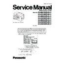
Panasonic KX-MB1900RUB-V1 / KX-MB1900RUW-V1 / KX-MB2000RUB-V1 / KX-MB2000RUW-V1 / KX-MB2020RUB-V1 / KX-MB2020RUW-V1 / KX-MB2030RUW-V1 Service Manual ▷ View online
ORDER NO.KMF1102344CE
Multi-Function printer
Model No.
KX-MB1900RUB-V1
KX-MB1900RUW-V1
KX-MB2000RUB-V1
KX-MB2000RUW-V1
KX-MB2020RUB-V1
KX-MB2020RUW-V1
KX-MB2030RUW-V1
KX-MB1900RUW-V1
KX-MB2000RUB-V1
KX-MB2000RUW-V1
KX-MB2020RUB-V1
KX-MB2020RUW-V1
KX-MB2030RUW-V1
(for Russia)
2
KX-MB1900RUB-V1/KX-MB1900RUW-V1/KX-MB2000RUB-V1/KX-MB2000RUW-V1/KX-MB2020RUB-V1/KX-MB2020RUW-V1/KX-MB2030RUW-V1
TABLE OF CONTENTS
PAGE
PAGE
1 Safety Precautions -----------------------------------------------6
1.1. For Service Technicians ----------------------------------6
1.2. AC Caution---------------------------------------------------6
1.3. Personal Safety Precautions ----------------------------7
1.2. AC Caution---------------------------------------------------6
1.3. Personal Safety Precautions ----------------------------7
1.3.1. Moving Sections of the Unit-------------------------7
1.3.2. Live Electrical Sections ------------------------------7
1.3.2. Live Electrical Sections ------------------------------7
1.4. Service Precautions ---------------------------------------7
1.4.1. Precautions to Prevent Damage from
Static Electricity ----------------------------------------7
2 Warning --------------------------------------------------------------8
2.1. About Lead Free Solder (PbF: Pb free) --------------8
2.1.1. Suggested PbF Solder -------------------------------8
2.2. Discarding of P. C. Board --------------------------------9
2.3. Insulation Resistance Test -------------------------------9
2.4. Battery Caution ---------------------------------------------9
2.5. Laser Beam And Fuser Unit Section ------------------9
2.6. Note for Repairing---------------------------------------- 10
2.3. Insulation Resistance Test -------------------------------9
2.4. Battery Caution ---------------------------------------------9
2.5. Laser Beam And Fuser Unit Section ------------------9
2.6. Note for Repairing---------------------------------------- 10
3 Specifications ---------------------------------------------------- 11
4 General/Introduction ------------------------------------------- 12
4 General/Introduction ------------------------------------------- 12
4.1. Optional Accessories------------------------------------ 12
4.2. Translation Lists ------------------------------------------ 12
4.2. Translation Lists ------------------------------------------ 12
4.2.1. Help Function----------------------------------------- 12
4.2.2. Error Message (Report)---------------------------- 12
4.2.3. Error Message (Display)--------------------------- 13
4.2.2. Error Message (Report)---------------------------- 12
4.2.3. Error Message (Display)--------------------------- 13
5 Features ------------------------------------------------------------ 14
5.1. General Features----------------------------------------- 14
5.2. Hardware Requirements for Multi-Function
5.2. Hardware Requirements for Multi-Function
Software ---------------------------------------------------- 14
6 Technical Descriptions---------------------------------------- 15
6.1. Connection Diagram------------------------------------- 15
6.2. General Block Diagram--------------------------------- 16
6.3. Main Board Section-------------------------------------- 18
6.2. General Block Diagram--------------------------------- 16
6.3. Main Board Section-------------------------------------- 18
6.3.1. Data Flow---------------------------------------------- 18
6.3.2. RTC Backup Circuit--------------------------------- 27
6.3.3. Modem Circuit Operation (KX-MB2020/
6.3.2. RTC Backup Circuit--------------------------------- 27
6.3.3. Modem Circuit Operation (KX-MB2020/
2030 ONLY)------------------------------------------- 28
6.3.4. TEL Line Section (KX-MB2020/2030
ONLY) -------------------------------------------------- 29
6.4. NCU Section (KX-MB2020/2030 ONLY) ----------- 31
6.4.1. General ------------------------------------------------ 31
6.4.2. EXT. TEL. Line Relay (RLY100)----------------- 31
6.4.3. Bell Detection Circuit------------------------------- 31
6.4.4. Pulse Dial Circuit------------------------------------ 31
6.4.5. Line Amplifier and Side Tone Circuit ----------- 31
6.4.6. Calling Line Identification Circuit (FSK) ------- 32
6.4.7. Remote FAX Activation Circuit ------------------ 32
6.4.8. TAM Interface Circuit------------------------------- 32
6.5. ITS (Integrated telephone System) and
Monitor Section (KX-MB2020/2030 ONLY) ------- 33
6.5.1. General ------------------------------------------------ 33
6.6. CIS Control Section ------------------------------------- 34
6.7. Motor Drive Section ------------------------------------- 35
6.7. Motor Drive Section ------------------------------------- 35
6.7.1. Engine Motor Control Circuit --------------------- 35
6.7.2. Scanner Motor Drive Circuit---------------------- 37
6.7.2. Scanner Motor Drive Circuit---------------------- 37
6.8. Timing chart and wave form of scanner
motors ------------------------------------------------------ 40
6.8.1. Normal 1-2 phase excitation (half step) ------- 40
6.8.2. Flat torque 1-2 phase excitation (half step) -- 41
6.8.3. W1-2 phase excitation (Quarter step) --------- 42
6.8.4. Drive mode of FB and ADF motor -------------- 43
6.8.2. Flat torque 1-2 phase excitation (half step) -- 41
6.8.3. W1-2 phase excitation (Quarter step) --------- 42
6.8.4. Drive mode of FB and ADF motor -------------- 43
6.9. FAN Motor Section -------------------------------------- 44
6.9.1. General ------------------------------------------------ 44
6.9.2. Circuit Diagram of FAN ---------------------------- 44
6.9.3. Fan Control ------------------------------------------- 44
6.9.4. Control table------------------------------------------ 45
6.9.5. Waveform --------------------------------------------- 46
6.9.2. Circuit Diagram of FAN ---------------------------- 44
6.9.3. Fan Control ------------------------------------------- 44
6.9.4. Control table------------------------------------------ 45
6.9.5. Waveform --------------------------------------------- 46
6.10. Solenoid Driver Section -------------------------------- 47
6.11. LSU (Laser Scanning Unit) Section----------------- 48
6.12. Sensors and Switches Section----------------------- 50
6.12.1. Drum Detection ------------------------------------- 51
6.12.2. Pickup Sensor --------------------------------------- 51
6.12.3. Exit Sensor ------------------------------------------- 52
6.12.4. Read Position Sensor------------------------------ 52
6.12.5. Registration & Manual Paper Sensor (KX-
6.12.2. Pickup Sensor --------------------------------------- 51
6.12.3. Exit Sensor ------------------------------------------- 52
6.12.4. Read Position Sensor------------------------------ 52
6.12.5. Registration & Manual Paper Sensor (KX-
MB2030 ONLY)-------------------------------------- 53
6.12.6. Print Timing Sensor -------------------------------- 53
6.12.7. Document Sensor (KX-MB2030 ONLY)------- 54
6.12.8. Top Cover Sensor----------------------------------- 54
6.12.7. Document Sensor (KX-MB2030 ONLY)------- 54
6.12.8. Top Cover Sensor----------------------------------- 54
3
KX-MB1900RUB-V1/KX-MB1900RUW-V1/KX-MB2000RUB-V1/KX-MB2000RUW-V1/KX-MB2020RUB-V1/KX-MB2020RUW-V1/KX-MB2030RUW-V1
6.12.9. Toner Sensor.... “Toner Empty”, “Toner
Low”, “Change Drum”-------------------------------55
6.12.10. Handset Hook Switch (KX-MB2020/2030
ONLY)---------------------------------------------------58
6.13. Operation Board Section -------------------------------58
6.14. LCD Section -----------------------------------------------59
6.15. HVPS (High Voltage Power Supply) Section ------60
6.14. LCD Section -----------------------------------------------59
6.15. HVPS (High Voltage Power Supply) Section ------60
6.15.1. HVPS Specification----------------------------------60
6.15.2. CHG-BIAS (Charge BIAS)/GRID/ UNIT--------60
6.15.3. DEV DC BIAS UNIT---------------------------------61
6.15.4. DEV AC BIAS UNIT---------------------------------61
6.15.5. TRA (+) BIAS (Transfer (+) BIAS)/TRA (-)
6.15.2. CHG-BIAS (Charge BIAS)/GRID/ UNIT--------60
6.15.3. DEV DC BIAS UNIT---------------------------------61
6.15.4. DEV AC BIAS UNIT---------------------------------61
6.15.5. TRA (+) BIAS (Transfer (+) BIAS)/TRA (-)
BIAS (Transfer (-) BIAS) UNIT -------------------61
6.16. Heat Lamp Control Circuit------------------------------62
6.17. Main Board Power Supply Section-------------------67
6.17. Main Board Power Supply Section-------------------67
6.17.1. 3.3V and 1.2V Power Supply ---------------------67
6.17.2. 5V Power Supply ------------------------------------68
6.17.3. Block Diagram of each Power Supply ----------68
6.17.2. 5V Power Supply ------------------------------------68
6.17.3. Block Diagram of each Power Supply ----------68
6.18. Power Supply Board Section --------------------------70
6.19. Mechanical Operation -----------------------------------71
6.19. Mechanical Operation -----------------------------------71
6.19.1. Printing -------------------------------------------------71
6.19.2. Scanning (ADF) (KX-MB2030 ONLY) ----------72
6.19.2. Scanning (ADF) (KX-MB2030 ONLY) ----------72
7 Location of Controls and Components ------------------73
7.1. Overview----------------------------------------------------73
7.1.1. Front view----------------------------------------------73
7.1.2. Rear view ----------------------------------------------74
7.1.2. Rear view ----------------------------------------------74
7.2. Control Panel ----------------------------------------------75
8 Installation Instructions ---------------------------------------76
8.1. Installation --------------------------------------------------76
8.1.1. Installation Space ------------------------------------76
8.1.2. OUTPUT TRAY---------------------------------------77
8.1.3. RECORDING PAPER------------------------------78
8.1.4. Documents the Unit Can Send -------------------82
8.1.5. Toner Cartridge and the Drum Cartridge-------83
8.1.6. Connecting to a computer -------------------------87
8.1.7. Installing Multi-Function Station -----------------87
8.2. Connections------------------------------------------------89
9 Operating Instructions-----------------------------------------91
9.1. Your Logo (KX-MB2020/2030 ONLY)---------------91
9.2. To Select Characters with the Dial Keypad --------92
9.2. To Select Characters with the Dial Keypad --------92
9.2.1. To Select Characters Using [] or []---------------92
10 Test Mode ----------------------------------------------------------93
10.1. Test Functions ---------------------------------------------93
10.1.1. DTMF Single Tone Transmit Selection
(KX-MB2020/2030 ONLY) -------------------------95
10.1.2. Button Code Table (KX-MB2020/2030
ONLY)---------------------------------------------------95
10.1.3. Button Code Table (KX-MB1900/2000) --------95
10.1.4. Print Test Pattern ------------------------------------96
10.1.4. Print Test Pattern ------------------------------------96
11 Service Mode -----------------------------------------------------97
11.1. Programming and Lists ---------------------------------97
11.1.1. Operation ----------------------------------------------97
11.1.2. Operation Flow ---------------------------------------97
11.1.3. Service Function Table (KX-MB2020/
11.1.2. Operation Flow ---------------------------------------97
11.1.3. Service Function Table (KX-MB2020/
2030)----------------------------------------------------98
11.1.4. Service Function Table (KX-MB1900/
2000)-------------------------------------------------- 100
11.1.5. Memory Clear Specification --------------------- 100
11.2. User Mode (The list below is an example of
the SYSTEM SETUP LIST the unit prints out.) - 101
11.3. Service Mode Settings (Example of a printed
out list) ---------------------------------------------------- 107
11.4. History (Example of a printed out list)------------- 109
11.4.1. Descriptions of The History Report ------------110
12 Troubleshooting Guide --------------------------------------111
12.1. User Recoverable Errors------------------------------ 111
12.2. Remote Programming (KX-MB2020/2030
12.2. Remote Programming (KX-MB2020/2030
ONLY)------------------------------------------------------114
12.2.1. Entering the Remote Programming Mode
and Changing Service Codes (KX-
MB2020/2030 ONLY)------------------------------115
MB2020/2030 ONLY)------------------------------115
12.2.2. Program Mode Table ------------------------------116
12.3. Troubleshooting Details ------------------------------ 121
12.3.1. Outline ----------------------------------------------- 121
12.3.2. Starting Troubleshooting------------------------- 121
12.3.3. Initialization ----------------------------------------- 122
12.3.4. Simple Check List --------------------------------- 123
12.3.5. Simplified Troubleshooting Guide ------------- 124
12.3.6. CALL SERVICE Troubleshooting Guide ---- 127
12.3.7. Print--------------------------------------------------- 134
12.3.8. Recording Paper Feed--------------------------- 140
12.3.9. ADF (Auto Document Feeder) Section
(KX-MB2030 ONLY) ------------------------------ 146
12.3.10. Communication Section (KX-MB2020/
2030 ONLY) ---------------------------------------- 152
12.3.11. Special Service Journal Reports (KX-
MB2020/2030 ONLY)----------------------------- 157
12.3.12. Initializing Error ------------------------------------ 170
12.3.13. Analog Section (KX-MB2020/2030 ONLY) - 171
12.3.14. Operation Panel Section ------------------------ 174
12.3.15. Sensor Section------------------------------------- 174
12.3.16. Motor Section -------------------------------------- 177
12.3.17. LSU Section ---------------------------------------- 181
12.3.18. CIS Control Section------------------------------- 182
12.3.19. High Voltage Value Check Point--------------- 184
12.3.20. High Voltage Section ----------------------------- 186
12.3.21. USB Section ---------------------------------------- 191
12.3.22. LAN SECTION (KX-MB2000/2020/2030
ONLY) ------------------------------------------------ 195
12.3.23. Main Board Section------------------------------- 199
12.3.24. Power Supply Board Section------------------- 202
12.3.24. Power Supply Board Section------------------- 202
12.4. DOCUMENT JAMS (AUTO DOCUMENT
FEEDER)------------------------------------------------- 205
12.5. RECORDING PAPER JAM-------------------------- 207
12.5.1. When the recording paper has jammed
inside of the unit ----------------------------------- 207
12.5.2. When the recording paper is not fed into
the unit properly ----------------------------------- 213
12.5.3. When the recording paper in the manual
input tray is not fed into the unit properly---- 214
13 Service Fixture & Tools ------------------------------------- 215
14 Disassembly and Assembly Instructions------------- 216
14 Disassembly and Assembly Instructions------------- 216
14.1. Bottom Section ----------------------------------------- 217
14.2. Left Side Section --------------------------------------- 217
14.3. Operation Panel Section ----------------------------- 218
14.4. Open Top Cover ---------------------------------------- 218
14.5. Remove Operation Panel -------------------------- 219
14.6. Remove Operation Board---------------------------- 219
14.7. Remove Main Board ---------------------------------- 220
14.8. Remove Gear Chassis Section--------------------- 221
14.9. Remove Right Cover ---------------------------------- 222
4
KX-MB1900RUB-V1/KX-MB1900RUW-V1/KX-MB2000RUB-V1/KX-MB2000RUW-V1/KX-MB2020RUB-V1/KX-MB2020RUW-V1/KX-MB2030RUW-V1
14.10. Remove Right Cassette Guide --------------------- 222
14.11. Remove Bottom Plate--------------------------------- 223
14.12. Remove Laser Unit ------------------------------------ 223
14.13. Remove Pick up Roller ------------------------------- 224
14.14. Remove Low Voltage Power Board --------------- 225
14.15. Remove Mirror ------------------------------------------ 225
14.16. Remove High Voltage Power Board--------------- 226
14.17. Note for diseassebly----------------------------------- 226
14.17.1. Position of Installing LABEL/CIS HOME----- 226
14.18. Installation Position of The Lead ------------------- 227
14.18.1. Top Cover Section (1) ---------------------------- 227
14.18.2. Top Cover Section (2) ---------------------------- 228
14.18.3. Top Cover Section (3) ---------------------------- 229
14.18.4. Bottom Part Section (1) -------------------------- 230
14.18.5. Bottom Part Section (2) -------------------------- 231
14.18.6. Side Cabinet Section (1)------------------------- 232
14.18.7. Side Cabinet Section (2)------------------------- 233
14.18.8. Side Cabinet Section (3)------------------------- 234
14.18.9. Side Cabinet Section (4)------------------------- 235
14.18.10. AC Inlet Section------------------------------------ 235
15 Maintenance ---------------------------------------------------- 236
15.1. Maintenance Items and Component Locations- 236
15.1.1. Outline------------------------------------------------ 236
15.1.2. Maintenance Check Items/Component
15.1.2. Maintenance Check Items/Component
Locations -------------------------------------------- 236
15.2. Maintenance--------------------------------------------- 238
15.2.1. Cleaning the White Plates and Glass -------- 238
15.2.2. CLEANING THE DOCUMENT FEEDER
15.2.2. CLEANING THE DOCUMENT FEEDER
ROLLERS ------------------------------------------- 242
15.3. Printing Operation Principle ------------------------- 243
15.3.1. Process Chart and Process BIAS ------------- 243
15.3.2. CHARGING ----------------------------------------- 243
15.3.3. Exposing--------------------------------------------- 244
15.3.4. Developing and Transcription ------------------ 245
15.3.5. Cleaning of Transfer Roller --------------------- 246
15.3.6. Fixing ------------------------------------------------- 247
15.4. Terminal Guide of The ICs Transistors and
Diodes----------------------------------------------------- 248
15.4.1. Main Board------------------------------------------ 248
15.4.2. Operation Board ----------------------------------- 249
15.4.3. High Voltage Power Supply Board ------------ 249
15.4.4. Low Voltage Power Supply Board------------- 249
15.4.2. Operation Board ----------------------------------- 249
15.4.3. High Voltage Power Supply Board ------------ 249
15.4.4. Low Voltage Power Supply Board------------- 249
15.5. How to Replace the Flat Package IC ------------- 250
15.5.1. Preparation------------------------------------------ 250
15.5.2. Flat Package IC Removal Procedure -------- 250
15.5.3. Flat Package IC Installation Procedure ------ 251
15.5.4. Bridge Modification Procedure ----------------- 251
15.5.2. Flat Package IC Removal Procedure -------- 250
15.5.3. Flat Package IC Installation Procedure ------ 251
15.5.4. Bridge Modification Procedure ----------------- 251
15.6. Main Board Section------------------------------------ 252
15.6.1. NG Example ---------------------------------------- 253
15.7. Test Chart ------------------------------------------------ 254
15.7.1. ITU-T No.1 Test Chart---------------------------- 254
15.7.2. ITU-T No.2 Test Chart---------------------------- 255
15.7.2. ITU-T No.2 Test Chart---------------------------- 255
16 Schematic Diagram------------------------------------------- 257
16.1. For Schematic Diagram ------------------------------ 257
16.2. Main Board (KX-MB1900) --------------------------- 258
16.2. Main Board (KX-MB1900) --------------------------- 258
16.2.1. Main Board (1) ------------------------------------- 258
16.2.2. Main Board (2) ------------------------------------- 262
16.2.3. Main Board (3) ------------------------------------- 264
16.2.2. Main Board (2) ------------------------------------- 262
16.2.3. Main Board (3) ------------------------------------- 264
16.3. Main Board (KX-MB2000) --------------------------- 266
16.3.1. Main Board (1) ------------------------------------- 266
16.3.2. Main Board (2) ------------------------------------- 270
16.3.2. Main Board (2) ------------------------------------- 270
16.3.3. Main Board (3)--------------------------------------272
16.4. Main Board (KX-MB2020) ----------------------------274
16.4.1. Main Board (1)--------------------------------------274
16.4.2. Main Board (2)--------------------------------------278
16.4.3. Main Board (3)--------------------------------------280
16.4.4. Main Board (4)--------------------------------------282
16.4.2. Main Board (2)--------------------------------------278
16.4.3. Main Board (3)--------------------------------------280
16.4.4. Main Board (4)--------------------------------------282
16.5. Main Board (KX-MB2030) ----------------------------284
16.5.1. Main Board (1)--------------------------------------284
16.5.2. Main Board (2)--------------------------------------288
16.5.3. Main Board (3)--------------------------------------290
16.5.4. Main Board (4)--------------------------------------292
16.5.2. Main Board (2)--------------------------------------288
16.5.3. Main Board (3)--------------------------------------290
16.5.4. Main Board (4)--------------------------------------292
16.6. Operation Board (KX-MB1900/2000)-------------- 294
16.7. Operation Board (KX-MB2020/2030)-------------- 295
16.8. Sensor Board --------------------------------------------296
16.9. High Voltage Power Supply Board -----------------297
16.7. Operation Board (KX-MB2020/2030)-------------- 295
16.8. Sensor Board --------------------------------------------296
16.9. High Voltage Power Supply Board -----------------297
16.10. Low Voltage Power Supply Board------------------298
17 Printed Circuit Board-----------------------------------------299
17.1. Main Board (KX-MB1900/2000) --------------------299
17.1.1. Main Board: Component View------------------299
17.1.2. Main Board: Bottom View------------------------300
17.1.2. Main Board: Bottom View------------------------300
17.2. Main Board (KX-MB2020/2030) --------------------301
17.2.1. Main Board: Component View------------------301
17.2.2. Main Board: Bottom View------------------------302
17.2.2. Main Board: Bottom View------------------------302
17.3. Operation Board ----------------------------------------303
17.3.1. Operation Board------------------------------------303
17.4. Sensor Board --------------------------------------------304
17.4.1. Toner Sensor Board ------------------------------- 304
17.4.2. Fuser Board -----------------------------------------304
17.4.3. Pickup Sensor Board -----------------------------304
17.4.4. Registration Sensor Board ----------------------305
17.4.5. Varistor Sensor Board ----------------------------305
17.4.6. ADF Sensor Board (KX-MB2030 ONLY)-----305
17.4.7. Handset Relay Board (KX-MB2020/2030
ONLY)-------------------------------------------------306
17.5. High Voltage Power Supply Board -----------------307
17.5.1. HIGH VOLTAGE POWER SUPPLY
BOARD: COMPONENT VIEW -----------------307
17.5.2. HIGH VOLTAGE POWER SUPPLY
BOARD: BOTTOM VIEW ------------------------307
17.6. Low Voltage Power Supply Board------------------308
17.6.1. LOW VOLTAGE POWER SUPPLY
BOARD: COMPONENT VIEW -----------------308
17.6.2. LOW VOLTAGE POWER SUPPLY
BOARD: BOTTOM VIEW ------------------------308
18 Exploded View and Replacement Parts List----------309
18.1. Cabinet, Mechanical and Electrical Parts
Location ---------------------------------------------------309
18.1.1. Operation Panel Section -------------------------309
18.1.2. ADF Section (KX-MB2030)----------------------310
18.1.3. Flatbet Section (KX-MB1900/2000/2020)---- 311
18.1.4. ADF Gear Section (KX-MB2030) -------------- 312
18.1.5. Top Cover Section --------------------------------313
18.1.6. Main Cabinet Section -----------------------------314
18.1.7. Fuser Section --------------------------------------- 315
18.1.8. Bottom Cabinet Section (1)----------------------316
18.1.9. Separation (DFP) Roller Section---------------317
18.1.10. Side Cabinet Section------------------------------318
18.1.11. Motor Section --------------------------------------- 319
18.1.12. Bottom Cabinet Section (2)----------------------320
18.1.13. Output Tray Section ------------------------------- 321
18.1.14. Actual Size of Screws and Washer------------322
18.1.13. Output Tray Section ------------------------------- 321
18.1.14. Actual Size of Screws and Washer------------322

