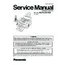
Panasonic KX-FLC413UA Service Manual ▷ View online
ORDER NO. KMF0903228CE
Compact Laser Fax
Model No.
KX-FLC413UA
(for Ukraine)
2
KX-FLC413UA
TABLE OF CONTENTS
PAGE
PAGE
1 Safety Precautions -----------------------------------------------5
1.1. For Service Technicians ----------------------------------5
1.2. AC Caution---------------------------------------------------5
1.3. Personal Safety Precautions ----------------------------6
1.2. AC Caution---------------------------------------------------5
1.3. Personal Safety Precautions ----------------------------6
1.3.1. Moving Sections of the Unit-------------------------6
1.3.2. Live Electrical Sections ------------------------------6
1.3.2. Live Electrical Sections ------------------------------6
1.4. Service Precautions ---------------------------------------6
1.4.1. Precautions to Prevent Damage from
Static Electricity ----------------------------------------6
1.5. For Best Performance-------------------------------------7
2 Warning --------------------------------------------------------------8
2.1. About Lead Free Solder (PbF: Pb free) --------------8
2.1.1. Suggested PbF Solder ------------------------------8
2.2. Discarding of P. C. Board --------------------------------8
2.3. Insulation Resistance Test -------------------------------9
2.4. Battery Caution ---------------------------------------------9
2.5. Laser Beam and Fuser Unit Section ---------------- 10
2.3. Insulation Resistance Test -------------------------------9
2.4. Battery Caution ---------------------------------------------9
2.5. Laser Beam and Fuser Unit Section ---------------- 10
3 Specifications ---------------------------------------------------- 11
3.1. Base Unit--------------------------------------------------- 11
3.2. Cordless Handset ---------------------------------------- 12
3.3. Charger Unit----------------------------------------------- 12
3.2. Cordless Handset ---------------------------------------- 12
3.3. Charger Unit----------------------------------------------- 12
4 General/Introduction ------------------------------------------- 12
4.1. Optional Accessories------------------------------------ 12
4.2. Translation List-------------------------------------------- 13
4.2. Translation List-------------------------------------------- 13
4.2.1. Help Function----------------------------------------- 13
4.2.2. Error Message (Reports) -------------------------- 13
4.2.3. Error Message (Display)--------------------------- 14
4.2.4. Cordless Handset ----------------------------------- 15
4.2.2. Error Message (Reports) -------------------------- 13
4.2.3. Error Message (Display)--------------------------- 14
4.2.4. Cordless Handset ----------------------------------- 15
5 Features ------------------------------------------------------------ 16
6 Technical Descriptions---------------------------------------- 17
6 Technical Descriptions---------------------------------------- 17
6.1. Connection Diagram------------------------------------- 17
6.2. General Block Diagram--------------------------------- 18
6.3. Facsimile Section ---------------------------------------- 20
6.2. General Block Diagram--------------------------------- 18
6.3. Facsimile Section ---------------------------------------- 20
6.3.1. Digital Section ---------------------------------------- 20
6.3.2. RTC Backup Circuit--------------------------------- 25
6.3.3. Modem Circuit Operation-------------------------- 26
6.3.2. RTC Backup Circuit--------------------------------- 25
6.3.3. Modem Circuit Operation-------------------------- 26
6.4. Modem Section ------------------------------------------- 27
6.4.1. Function------------------------------------------------ 27
6.5. NCU Section----------------------------------------------- 33
6.5.1. General ------------------------------------------------ 33
6.5.2. EXT. TEL. Line Relay (RLY200) ----------------- 33
6.5.3. Bell Detection Circuit ------------------------------- 33
6.5.4. Calling Line Identification Circuit ---------------- 33
6.5.5. Line Amplifier and Side Tone Circuit------------ 34
6.5.6. Remote Fax Activation Circuit-------------------- 34
6.6. ITS (Integrated Telephone System) and
Monitor Section ------------------------------------------- 35
6.6.1. General ------------------------------------------------ 35
6.7. CIS Control Section-------------------------------------- 36
6.8. Stepping Motor Drive Section ------------------------- 37
6.8. Stepping Motor Drive Section ------------------------- 37
6.8.1. Engine Motor Drive Circuit ------------------------ 37
6.8.2. Scan Motor Drive Circuit--------------------------- 39
6.8.2. Scan Motor Drive Circuit--------------------------- 39
6.9. FAN Motor Section--------------------------------------- 41
6.9.1. FAN Control------------------------------------------- 41
6.10. Solenoid Drive Section --------------------------------- 42
6.11. LSU (Laser Scanning Unit) Section ----------------- 43
6.12. Sensors and Switches Section ----------------------- 45
6.12.1. Hook Switch ------------------------------------------ 45
6.12.2. Document Sensor----------------------------------- 45
6.12.3. Paper Feed Sensor--------------------------------- 46
6.12.4. Top Cover Open Switch --------------------------- 46
6.12.5. Drum Sensor ----------------------------------------- 47
6.12.6. Regist Sensor---------------------------------------- 47
6.12.7. Paper Sensor..... "OUT OF PAPER" ----------- 48
6.12.8. Paper Exit Sensor..... "PAPER JAMMED" ---- 48
6.12.9. Drum Detection-------------------------------------- 49
6.12.10. Toner Sensor.... "TONER EMPTY",
"TONER LOW", "CHANGE DRUM" ------------ 50
6.13. Operation Board Section ------------------------------ 52
6.14. LCD Section----------------------------------------------- 53
6.15. Transmitter / Receiver (Cordless) ------------------- 54
6.14. LCD Section----------------------------------------------- 53
6.15. Transmitter / Receiver (Cordless) ------------------- 54
6.15.1. Transmitter Block ----------------------------------- 54
6.15.2. Receiver Block--------------------------------------- 54
6.15.3. Power Supply Circuit (Cordless Base Unit) -- 54
6.15.2. Receiver Block--------------------------------------- 54
6.15.3. Power Supply Circuit (Cordless Base Unit) -- 54
6.16. Cordless Handset Section----------------------------- 55
6.16.1. Cordless Handset Block Diagram -------------- 55
6.16.2. Cordless Handset Circuit Operation ----------- 56
6.16.3. Charger Unit Circuit Operation ------------------ 56
6.16.2. Cordless Handset Circuit Operation ----------- 56
6.16.3. Charger Unit Circuit Operation ------------------ 56
6.17. HVPS (High Voltage Power Supply) Section ----- 57
6.17.1. HVPS Specification--------------------------------- 57
6.17.2. CHG-BIAS (Charge BIAS)/GRID Unit --------- 58
6.17.3. TRA(+) BIAS (Transfer(+) BIAS)/TRA(-)
6.17.2. CHG-BIAS (Charge BIAS)/GRID Unit --------- 58
6.17.3. TRA(+) BIAS (Transfer(+) BIAS)/TRA(-)
BIAS (Transfer(-) BIAS) Unit --------------------- 58
6.18. Heat Lamp Control Circuit----------------------------- 59
6.19. Power Supply Board Section ------------------------- 65
6.19. Power Supply Board Section ------------------------- 65
7 Location of Controls and Components ----------------- 68
7.1. Overview --------------------------------------------------- 68
7.1.1. Base Unit---------------------------------------------- 68
7.1.2. Cordless Handset----------------------------------- 68
7.1.2. Cordless Handset----------------------------------- 68
7.2. Control Panel --------------------------------------------- 69
7.2.1. Base Unit---------------------------------------------- 69
7.2.2. Cordless Handset----------------------------------- 70
7.2.2. Cordless Handset----------------------------------- 70
8 Installation Instructions -------------------------------------- 71
8.1. Installation Space ---------------------------------------- 71
8.2. Connections----------------------------------------------- 72
8.2. Connections----------------------------------------------- 72
8.2.1. Base Unit---------------------------------------------- 72
8.2.2. Charger Unit------------------------------------------ 72
8.2.2. Charger Unit------------------------------------------ 72
8.3. Battery Charge ------------------------------------------- 73
8.4. Paper Stacker--------------------------------------------- 73
8.5. Document Stacker--------------------------------------- 74
8.6. Paper Tray------------------------------------------------- 74
8.7. Recording Paper ----------------------------------------- 75
8.8. Document Requirements ------------------------------ 77
8.9. Replacing the Toner Cartridge and the Drum
Unit ---------------------------------------------------------- 78
8.10. Battery Installation / Replacement------------------- 83
9 Operation Instructions---------------------------------------- 84
9.1. Characters available in each character entry
mode-------------------------------------------------------- 84
9.2. Setting Your Logo---------------------------------------- 85
9.3. Cordless Handset Programming--------------------- 86
9.3. Cordless Handset Programming--------------------- 86
9.3.1. Cordless Handset Features ---------------------- 86
9.4. Registering a Cordless Handset to a Base
Unit ---------------------------------------------------------- 87
9.4.1. Cancelling a Cordless Handset ----------------- 87
9.5. For Service Hint ------------------------------------------ 87
3
KX-FLC413UA
10 Test Mode ----------------------------------------------------------88
10.1. Test Functions ---------------------------------------------88
10.1.1. Button Code Table-----------------------------------90
10.1.2. Print Test Pattern ------------------------------------91
10.1.2. Print Test Pattern ------------------------------------91
11 Service Mode -----------------------------------------------------92
11.1. Programming and Lists ---------------------------------92
11.1.1. Operation ----------------------------------------------92
11.1.2. Operation Flow ---------------------------------------92
11.1.3. Service Function Table -----------------------------93
11.1.4. Memory Clear Specification -----------------------95
11.1.2. Operation Flow ---------------------------------------92
11.1.3. Service Function Table -----------------------------93
11.1.4. Memory Clear Specification -----------------------95
11.2. Cordless Handset ----------------------------------------96
11.3. The Example of the Printed List ----------------------98
11.3. The Example of the Printed List ----------------------98
11.3.1. User Mode (The list below is an example
of the SYSTEM SETUP LIST the unit
prints out.) ---------------------------------------------98
prints out.) ---------------------------------------------98
11.3.2. Service Mode Settings (Example of a
printed out list)----------------------------------------99
11.3.3. History (Example of a printed out list) -------- 100
12 Troubleshooting Guide -------------------------------------- 102
12.1. User Recoverable Errors ----------------------------- 102
12.1.1. Base Unit -------------------------------------------- 102
12.1.2. Cordless Handset---------------------------------- 103
12.1.2. Cordless Handset---------------------------------- 103
12.2. Error Messages-Report ------------------------------- 104
12.2.1. Journal Report-------------------------------------- 104
12.2.2. Special Service Journal Reports --------------- 113
12.2.3. Communication Section-------------------------- 116
12.2.4. Initializing Error------------------------------------- 121
12.2.5. Analog Board Section ---------------------------- 122
12.2.6. CIS (Contact Image Sensor) Section --------- 130
12.2.7. High Voltage Value Check Point --------------- 131
12.2.8. High Voltage Section------------------------------ 133
12.2.9. Power Supply Board Section ------------------- 138
12.3. Remote Programming --------------------------------- 141
12.3.1. Entering the Remote Programming Mode
and Changing Service Codes ------------------ 142
12.3.2. Program Mode Table------------------------------ 143
12.4. Troubleshooting Details ------------------------------- 145
12.4.1. Outline ------------------------------------------------ 145
12.4.2. Starting Troubleshooting ------------------------- 145
12.4.3. Initialization------------------------------------------ 146
12.4.4. Simple Check List --------------------------------- 147
12.4.5. Simplified Troubleshooting Guide ------------- 148
12.4.6. Call Service Troubleshooting Guide ---------- 152
12.4.7. Print --------------------------------------------------- 158
12.4.8. Recording Paper Feed --------------------------- 166
12.4.9. ADF (Auto Document Feed) Section --------- 171
12.4.10. Cordless Section----------------------------------- 178
12.4.11. Troubleshooting by Symptom (Cordless
Handset) --------------------------------------------- 185
12.4.12. Troubleshooting by Symptom (Cordless
Base Unit) ------------------------------------------- 188
12.4.13. Troubleshooting by Symptom (Charger
Unit) --------------------------------------------------- 190
13 Service Fixture & Tools-------------------------------------- 191
14 Disassembly and Assembly Instructions ------------- 192
14 Disassembly and Assembly Instructions ------------- 192
14.1. Upper Main Cabinet Section------------------------- 193
14.2. Lower Main Cabinet Section------------------------- 194
14.3. Cordless Handset Section---------------------------- 195
14.4. How to Remove the Front Cover ------------------- 196
14.5. How to Remove the Pick Up Unit------------------- 197
14.6. How to Remove the Pick Up Roller ---------------- 198
14.7. How to Remove the Antenna Board--------------- 199
14.8. How to Remove the Operation Board------------- 200
14.9. How to Remove the Lower Flame ----------------- 201
14.8. How to Remove the Operation Board------------- 200
14.9. How to Remove the Lower Flame ----------------- 201
14.10. How to Remove the Separation Rubber --------- 201
14.11. How to Remove the Transfer Roller--------------- 202
14.12. How to Remove the Separation Roller ----------- 203
14.13. How to Remove the Bottom Plate ----------------- 204
14.14. How to Remove the Analog Board ---------------- 204
14.15. How to Remove the RF Unit ------------------------ 205
14.16. How to Remove the High Voltage Power
14.13. How to Remove the Bottom Plate ----------------- 204
14.14. How to Remove the Analog Board ---------------- 204
14.15. How to Remove the RF Unit ------------------------ 205
14.16. How to Remove the High Voltage Power
Board------------------------------------------------------ 205
14.17. How to Remove the Laser Unit--------------------- 206
14.18. How to Remove the Fan Unit ----------------------- 206
14.19. How to Remove the Low Voltage Power
14.18. How to Remove the Fan Unit ----------------------- 206
14.19. How to Remove the Low Voltage Power
Board------------------------------------------------------ 207
14.20. How to Remove the Digital Board ----------------- 207
14.21. How to Remove the Main Motor-------------------- 208
14.22. How to Remove the Fuser Unit--------------------- 209
14.23. How to Remove the CIS------------------------------ 210
14.24. Installation Position of the Lead ---------------------211
14.25. How to Remove the Cordless Handset Board-- 216
14.25.1. How to Replace the LCD ------------------------ 217
14.26. How to Remove the Charger Board--------------- 218
15 Measurements and Adjustments ------------------------ 219
15.1. Cordless Base Section Adjustment---------------- 219
15.1.1. Equipment Required ----------------------------- 219
15.1.2. PC Setting------------------------------------------- 219
15.1.3. How to Adjust -------------------------------------- 220
15.1.4. Frequency and Voltage Adjustment ---------- 221
15.1.2. PC Setting------------------------------------------- 219
15.1.3. How to Adjust -------------------------------------- 220
15.1.4. Frequency and Voltage Adjustment ---------- 221
15.2. Adjustment Standard (Cordless Base Unit) ----- 223
15.3. Adjustment Standard (Charger Unit) -------------- 224
15.3. Adjustment Standard (Charger Unit) -------------- 224
15.3.1. Flow Solder Side View --------------------------- 224
15.4. The Setting Method of JIG (Cordless
Handset)-------------------------------------------------- 225
15.4.1. Preparation------------------------------------------ 225
15.4.2. PC Setting------------------------------------------- 225
15.4.2. PC Setting------------------------------------------- 225
15.5. Adjustment Standard (Cordless Handset) ------- 227
15.5.1. Component View ---------------------------------- 227
15.6. Things to Do after Replacing IC -------------------- 228
15.6.1. Base Unit -------------------------------------------- 228
15.6.2. Cordless Handset --------------------------------- 228
15.6.2. Cordless Handset --------------------------------- 228
15.7. RF Specification ---------------------------------------- 229
15.7.1. Base Unit -------------------------------------------- 229
15.7.2. Cordless Handset --------------------------------- 229
15.7.2. Cordless Handset --------------------------------- 229
15.8. How to Check the Cordless Handset Speaker
or Receiver ---------------------------------------------- 230
15.9. Frequency Table (MHz)------------------------------- 230
16 Maintenance ---------------------------------------------------- 231
16.1. Maintenance Items and Component Locations- 231
16.1.1. Outlines ---------------------------------------------- 231
16.1.2. Maintenance Check Items/Component
16.1.2. Maintenance Check Items/Component
Locations -------------------------------------------- 231
16.2. Printing---------------------------------------------------- 233
16.3. Printing (Paper Pick Up)------------------------------ 234
16.4. Scanning (ADF) ---------------------------------------- 235
16.5. Maintenance--------------------------------------------- 236
16.3. Printing (Paper Pick Up)------------------------------ 234
16.4. Scanning (ADF) ---------------------------------------- 235
16.5. Maintenance--------------------------------------------- 236
16.5.1. Cleaning the Inside of the Unit ---------------- 236
16.6. Document Jams ---------------------------------------- 239
16.7. Recording Paper Jams ------------------------------- 241
16.7. Recording Paper Jams ------------------------------- 241
16.7.1. When the recording paper has jammed
near the drum and toner unit ------------------- 241
4
KX-FLC413UA
16.7.2. When the recording paper has jammed
near the recording paper exit: ------------------ 242
16.7.3. When the recording paper is not fed into
the unit properly------------------------------------ 244
16.8. Printing Operation Principle ------------------------- 245
16.8.1. Process Chart and Process Bias -------------- 245
16.8.2. Charging --------------------------------------------- 245
16.8.3. Exposing--------------------------------------------- 246
16.8.4. Laser Scanning Unit Locations ---------------- 246
16.8.5. Developing and Transcription ------------------ 247
16.8.6. Cleaning of Transfer Roller --------------------- 248
16.8.7. Fixing ------------------------------------------------- 249
16.8.8. Timing Chart (When Printing Two Sheets
of Paper) BASIC ----------------------------------- 250
16.8.9. Timing Chart [Initializing (Long)]--------------- 251
16.8.10. Timing Chart (when the registration sensor
is turned OFF then ON during initializing)--- 252
16.9. Terminal Guide of the ICs Transistors and
Diodes----------------------------------------------------- 253
16.9.1. Digital Board ---------------------------------------- 253
16.9.2. Analog Board --------------------------------------- 254
16.9.3. Operation Board ----------------------------------- 254
16.9.4. High Voltage Power Supply Board ------------ 254
16.9.5. Low Voltage Power Supply Board------------- 255
16.9.6. Cordless Base Board----------------------------- 255
16.9.7. Cordless Handset Board ------------------------ 256
16.10. How to Replace the Flat Package IC ------------- 257
16.10.1. Preparation------------------------------------------ 257
16.10.2. Flat Package IC Removal Procedure -------- 257
16.10.3. Flat Package IC Installation Procedure ------ 258
16.10.4. Bridge Modification Procedure ----------------- 258
16.10.2. Flat Package IC Removal Procedure -------- 257
16.10.3. Flat Package IC Installation Procedure ------ 258
16.10.4. Bridge Modification Procedure ----------------- 258
16.11. Digital Board Section---------------------------------- 259
16.11.1. NG Example ---------------------------------------- 260
16.12. Test Chart ------------------------------------------------ 261
16.12.1. ITU-T No.1 Test Chart---------------------------- 261
16.12.2. ITU-T No.2 Test Chart---------------------------- 262
16.12.2. ITU-T No.2 Test Chart---------------------------- 262
17 Schematic Diagram------------------------------------------- 264
17.1. Digital Board (PCB1) ---------------------------------- 264
17.2. Analog Board (PCB2) --------------------------------- 268
17.3. Sensor Boards (PCB3-5)----------------------------- 270
17.4. Cordless Base Board (PCB6)----------------------- 271
17.5. Operation Board (PCB7) ----------------------------- 272
17.6. High Voltage Power Supply Board (PCB8) ------ 273
17.7. Low Voltage Power Supply Board (PCB9)------- 274
17.8. Cordless Handset Board (PCB10)----------------- 276
17.9. Charger Unit Board (PCB11) ------------------------ 278
18 Printed Circuit Board ---------------------------------------- 279
18.1. Digital Board (PCB1) ---------------------------------- 279
18.1.1. Component View ---------------------------------- 279
18.1.2. Bottom View ---------------------------------------- 280
18.1.2. Bottom View ---------------------------------------- 280
18.2. Analog Board (PCB2) --------------------------------- 281
18.2.1. Component View ---------------------------------- 281
18.2.2. Bottom View ---------------------------------------- 282
18.2.2. Bottom View ---------------------------------------- 282
18.3. Exit Sensor Board (PCB3) --------------------------- 283
18.4. Drum & Toner Sensor Board (PCB4) ------------- 283
18.5. Varistor Sensor Board (PCB5) ---------------------- 283
18.6. Cordless Base Board (PCB6)----------------------- 285
18.4. Drum & Toner Sensor Board (PCB4) ------------- 283
18.5. Varistor Sensor Board (PCB5) ---------------------- 283
18.6. Cordless Base Board (PCB6)----------------------- 285
18.6.1. Component View ---------------------------------- 285
18.6.2. Bottom View ---------------------------------------- 286
18.6.2. Bottom View ---------------------------------------- 286
18.7. Operation Board (PCB7) ----------------------------- 287
18.7.1. Component View ---------------------------------- 287
18.7.2. Bottom View -----------------------------------------288
18.8. High Voltage Power Supply Board (PCB8) ------289
18.8.1. Component View-----------------------------------289
18.8.2. Bottom View -----------------------------------------290
18.8.2. Bottom View -----------------------------------------290
18.9. Low Voltage Power Supply Board (PCB9) -------291
18.9.1. Component View-----------------------------------291
18.9.2. Bottom View -----------------------------------------292
18.9.2. Bottom View -----------------------------------------292
18.10. Cordless Handset Board (PCB10) -----------------293
18.10.1. Component View-----------------------------------293
18.10.2. Bottom View -----------------------------------------294
18.10.2. Bottom View -----------------------------------------294
18.11. Charger Unit Board (PCB11) ------------------------295
18.11.1. Component View-----------------------------------295
18.11.2. Bottom View -----------------------------------------295
18.11.2. Bottom View -----------------------------------------295
19 Appendix Information of Schematic Diagram -------296
20 Exploded View and Replacement Parts List----------297
20 Exploded View and Replacement Parts List----------297
20.1. Cabinet, Mechanical and Electrical Parts
Location ---------------------------------------------------297
20.1.1. General Section ------------------------------------297
20.1.2. Operation Cover Section (1) -------------------- 298
20.1.3. Operation Cover Section (2) -------------------- 299
20.1.4. Operation Cover Section (3) -------------------- 300
20.1.5. Pick Up Section ------------------------------------301
20.1.6. Fuser Section --------------------------------------- 302
20.1.7. Lower Main Cabinet Section (1)----------------303
20.1.8. Lower Main Cabinet Section (2)----------------304
20.1.9. Motor Section --------------------------------------- 305
20.1.10. Fan Motor Section ---------------------------------306
20.1.11. Lower Cabinet Section (3) -----------------------307
20.1.12. Gear Section ----------------------------------------308
20.1.13. Handset Section------------------------------------309
20.1.14. Charger Unit Section------------------------------310
20.1.15. Actual Size of Screws and Washer ----------- 311
20.1.16. Accessories and Packing Materials -----------312
20.1.13. Handset Section------------------------------------309
20.1.14. Charger Unit Section------------------------------310
20.1.15. Actual Size of Screws and Washer ----------- 311
20.1.16. Accessories and Packing Materials -----------312
20.2. Replacement Parts List -------------------------------313
20.2.1. Cabinet and Electrical Parts--------------------- 313
20.2.2. Digital Board Parts---------------------------------316
20.2.3. Analog Board Parts--------------------------------319
20.2.4. Exit Sensor Board Parts--------------------------320
20.2.5. Toner Sensor Board Parts -----------------------320
20.2.6. Varistor Sensor Board Parts--------------------- 321
20.2.7. Cordless Base Board Parts --------------------- 321
20.2.8. Operation Board Parts----------------------------322
20.2.9. High Voltage Power Supply Board Parts----- 323
20.2.10. Low Voltage Power Supply Board Parts ----- 323
20.2.11. Cordless Handset Board Parts -----------------323
20.2.12. Charger Board Parts ------------------------------325
20.2.13. Service Fixture and Tools ------------------------325
20.2.13. Service Fixture and Tools ------------------------325


