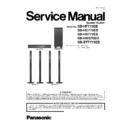
Panasonic SB-HF775EB / SB-HC775EB / SB-HS775EB / SB-HW370EG / SB-BTT775EB Service Manual ▷ View online
5
3 Disassembly and Assembly Instructions
“ATTENTION SERVICER”
Some chassis components may have sharp edges. Be careful when disassembling and servicing.
This section describes procedures for checking the operation and replacing the main components.
For reassembly after operation checks or replacement, reverse the respective procedures.
For reassembly after operation checks or replacement, reverse the respective procedures.
Special reassembly procedures are described only when required.
Select items from the following index when checks or replacement are required.
Refer to the Parts No. on the page of “Exploded View and Replacement Parts List” (Section 5), if necessary.
Refer to the Parts No. on the page of “Exploded View and Replacement Parts List” (Section 5), if necessary.
Below is the list of disassembly sections
• Front Speakers (SB-HS775EB-K)
Disassembly of Upper Box Assembly
Disassembly of Upper Rear Cabinet Assembly
Disassembly of Tweeter Speaker (SP41)
Disassembly of Woofer Speaker (SP42)
Disassembly of Woofer Speaker (SP43)
Disassembly of Lower Box Assembly
Disassembly of Speaker Wire
Disassembly of Base Cover
Disassembly of Upper Rear Cabinet Assembly
Disassembly of Tweeter Speaker (SP41)
Disassembly of Woofer Speaker (SP42)
Disassembly of Woofer Speaker (SP43)
Disassembly of Lower Box Assembly
Disassembly of Speaker Wire
Disassembly of Base Cover
6
3.1.
Front Speakers (SB-HS775EB-K)
3.1.1.
Dissassembly of Upper Box Assembly
Step 1: Remove the White (+) and Bule (-) wires.
Step 2: Pull out the Speaker Wire from the groove.
Step 2: Pull out the Speaker Wire from the groove.
Step 3: Remove 1 screw from Upper Box Assembly.
Step 4: Detach the Upper Box Assembly.
7
3.1.2.
Disassembly of Upper Rear Cabinet Assembly
• Refer to “Disassembly of Upper Box Assembly”.
Step 1: Remove 11 screws.
Step 2: Flip the Rear Cabinet Assembly and place it by the side
of Front Panel Assembly.
Step 3: Detach the Red/Black (+) and Black/Yellow (-) wires.
Step 4: Remove Rear Cabinet Assembly.
of Front Panel Assembly.
Step 3: Detach the Red/Black (+) and Black/Yellow (-) wires.
Step 4: Remove Rear Cabinet Assembly.
Caution: Ensure that Speaker Wire is properly inserted in
the Slot.
the Slot.
8
3.1.3.
Disassembly of Tweeter Speaker (SP41)
• Refer to “Disassembly of Upper Box Assembly”.
• Follow (Step 1) to (Step 2) in item 3.1.2.
• Follow (Step 1) to (Step 2) in item 3.1.2.
Step 1: Remove 4 screws.
Step 2: Detach the Yellow (+) and Black (-) wires.
Step 3: Remove Tweeter Speaker (SP41).
Step 3: Remove Tweeter Speaker (SP41).
Caution: Ensure that Speaker Wire is properly inserted in
the Slot.
the Slot.
Click on the first or last page to see other SB-HF775EB / SB-HC775EB / SB-HS775EB / SB-HW370EG / SB-BTT775EB service manuals if exist.

