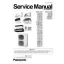
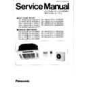
Panasonic S-22KA1E5 / S-28KA1E5 / S-36KA1E5 / S-45KA1E5 / S-56KA1E5 / S-63KA1E5 / S-71KA1E5 / S-22YA1E5 / S-28YA1E5 / S-36YA1E5 / S-45YA1E5 / S-56YA1E5 / S-22NA1E5 / S-28NA1E5 / S-32NA1E5 / S-36NA1E5 / S-45NA1E5 / S-56NA1E5 / S-45MA1E5 / S-56MA1E5 / S-63MA1E5 / S-7 Service Manual ▷ View online
Order No: RAC1001001C8
Indoor Unit
Outdoor Unit
S-22KA1E5
S-28KA1E5
S-36KA1E5
S-45KA1E5
S-56KA1E5
S-63KA1E5
S-71KA1E5
S-28KA1E5
S-36KA1E5
S-45KA1E5
S-56KA1E5
S-63KA1E5
S-71KA1E5
S-22KA1E5S
S-28KA1E5S
S-36KA1E5S
S-45KA1E5S
S-28KA1E5S
S-36KA1E5S
S-45KA1E5S
S-22YA1E5
S-28YA1E5
S-36YA1E5
S-45YA1E5
S-56YA1E5
S-28YA1E5
S-36YA1E5
S-45YA1E5
S-56YA1E5
S-63UA1E5
S-71UA1E5
S-90UA1E5
S-22NA1E5
S-28NA1E5
S-32NA1E5
S-36NA1E5
S-45NA1E5
S-56NA1E5
S-71UA1E5
S-90UA1E5
S-22NA1E5
S-28NA1E5
S-32NA1E5
S-36NA1E5
S-45NA1E5
S-56NA1E5
S-45MA1E5
S-56MA1E5
S-63MA1E5
S-71MA1E5
S-90MA1E5
S-56MA1E5
S-63MA1E5
S-71MA1E5
S-90MA1E5
U-4LA1E5
U-5LA1E5
U-6LA1E5
U-5LA1E5
U-6LA1E5
U-4LA1E5-1
U-5LA1E5-1
U-6LA1E5-1
U-5LA1E5-1
U-6LA1E5-1
PRECAUTION OF LOW TEMPERATURE
In order to avoid frostbite, be assured of no refrigerant leakage during the installation or repairing of refrigerant circuit.
WARNING
This service information is designed for experienced repair technicians only and is not designed for use by the general public.
It does not contain warnings or cautions to advise non-technical individuals of potential dangers in attempting to service a product.
Products powered by electricity should be serviced or repaired only by experienced professional technicians. Any attempt to
service or repair the products dealt with in this service information by anyone else could result in serious injury or death.
2
TABLE OF CONTENTS
1.
Safety Precautions .............................................5
2.
Features...............................................................7
3.
Product Specification ......................................13
3.1
Wall Mounted Type Indoor Unit – KA1E5 /
KA1E5S Series...........................................13
KA1E5S Series...........................................13
3.2
60 x 60 Cassette Type Indoor Unit – YA1E5
Series..........................................................19
Series..........................................................19
3.3
95 x 95 Cassette Type Indoor Unit – UA1E5
Series..........................................................23
Series..........................................................23
3.4
Slim Hide-Away Type Indoor Unit – NA1E5
Series..........................................................25
Series..........................................................25
3.5
Low Static Pressure Hide-Away Type Indoor
Unit – MA1E5 Series ..................................31
Unit – MA1E5 Series ..................................31
3.6
Outdoor Unit – LA1E5 Series .....................37
4.
Dimensions .......................................................39
4.1
Wall Mounted Type Indoor Unit..................39
4.2
60 x 60 Cassette Type Indoor Unit.............41
4.3
95 x 95 Cassette Type Indoor Unit.............42
4.4
Slim Hide-Away Type Indoor Unit ..............43
4.5
Low Static Pressure Hide-Away Type Indoor
Unit .............................................................44
Unit .............................................................44
4.6
Outdoor Unit ...............................................46
5.
Refrigeration Cycle Diagram ...........................47
6.
Block Diagram ..................................................48
6.1
Wall Mounted Type Indoor Unit – KA1E5
Series..........................................................48
Series..........................................................48
6.2
60 x 60 Cassette Type Indoor Unit – YA1E5
Series..........................................................48
Series..........................................................48
6.3
95 x 95 Cassette Type Indoor Unit – UA1E5
Series..........................................................49
Series..........................................................49
6.4
Slim Hide Away Type Indoor Unit – NA1E5
Series..........................................................49
Series..........................................................49
6.5
Low Static Pressure Hide Away Type Indoor
Unit – MA1E5 Series ..................................50
Unit – MA1E5 Series ..................................50
6.6
Outdoor Unit – LA1E5 Series .....................50
7.
Wiring Connection Diagram ............................51
7.1
Wall Mounted Type Indoor Unit – KA1E5
Series..........................................................51
Series..........................................................51
7.2
60 x 60 Cassette Type Indoor Unit – YA1E5
Series..........................................................52
Series..........................................................52
7.3
95 x 95 Cassette Type Indoor Unit – UA1E5
Series..........................................................53
Series..........................................................53
7.4
Slim Hide Away Type Indoor Unit – NA1E5
Series..........................................................54
Series..........................................................54
7.5
Low Static Pressure Hide Away Type Indoor
Unit – MA1E5 Series ..................................55
Unit – MA1E5 Series ..................................55
7.6
Outdoor Unit – LA1E5 Series .....................56
8.
Electronic Circuit Diagram ..............................57
8.1
Wall Mounted Type Indoor Unit – KA1E5
Series..........................................................57
Series..........................................................57
8.2
60 x 60 Cassette Type Indoor Unit – YA1E5
Series..........................................................59
Series..........................................................59
8.3
95 x 95 Cassette Type Indoor Unit – UA1E5
Series..........................................................61
Series..........................................................61
8.4
Slim Hide Away Type Indoor Unit – NA1E5
Series......................................................... 63
Series......................................................... 63
8.5
Low Static Pressure Hide Away Type Indoor
Unit – MA1E5 Series ................................. 65
Unit – MA1E5 Series ................................. 65
8.6
Outdoor Unit – LA1E5 Series .................... 67
9.
Printed Circuit Board ...................................... 69
9.1
Wall Mounted Type Indoor Unit – KA1E5
Series......................................................... 69
Series......................................................... 69
9.2
60 x 60 Cassette Type Indoor Unit – YA1E5
Series......................................................... 71
Series......................................................... 71
9.3
95 x 95 Cassette Type Indoor Unit – YA1E5
Series......................................................... 72
Series......................................................... 72
9.4
Slim Hide Away Type Indoor Unit – NA1E5
Series......................................................... 72
Series......................................................... 72
9.5
Low Static Pressure Hide Away Type Indoor
Unit – MA1E5 Series ................................. 73
Unit – MA1E5 Series ................................. 73
9.6
Outdoor Unit – LA1E5 Series .................... 74
10. Remote Control Operating Instructions........ 77
10.1
Wired remote control CZ-RT1 .................. 77
10.2
Wireless Remote Control CZ-RWS1 – Heat
Pump models / CZ-RWC1 – Cooling models .
................................................................... 78
Pump models / CZ-RWC1 – Cooling models .
................................................................... 78
11. Installation Instruction .................................... 79
11.1
Pipe Length ............................................... 79
11.2
Branch Pipe Connection CZ-P155BK1 ..... 80
11.3
Capacity Correction ................................... 81
11.4
INSTALLATION INSTRUCTIONS FS MULTI
WALL MOUNTED TYPE ........................... 82
WALL MOUNTED TYPE ........................... 82
11.5
INSTALLATION INSTRUCTIONS FS MULTI
FOUR-WAY MINI CASSETTE .................. 92
FOUR-WAY MINI CASSETTE .................. 92
11.6
INSTALLATION INSTRUCTIONS FS MULTI
FOUR-WAY CASSETTE ......................... 103
FOUR-WAY CASSETTE ......................... 103
11.7
CZ-RWRU1 Infrared Receiver (For Cassette
only) Installation Manual.......................... 114
only) Installation Manual.......................... 114
11.8
INSTALLATION INSTRUCTIONS FS MULTI
DUCT TYPE ............................................ 117
DUCT TYPE ............................................ 117
11.9
DUCT TYPE AIR CONDITIONERS
INSTALLATION INSTRUCTIONS........... 126
INSTALLATION INSTRUCTIONS........... 126
11.10 CZ-RWRM1 Infrared Receiver (For Ducted
series only) Installation Manual ............... 135
11.11 INFRARED REMOTE CONTROLLER
INSTALLATION MANUAL ....................... 138
11.12 WIRED CONTROLLER INSTALLATION
MANUAL CZ-RT1.................................... 142
11.13 INSTALLATION INSTRUCTIONS FS MULTI
OUTDOOR UNIT..................................... 151
11.14 INSTALLATION INSTRUCTIONS FS MULTI
OUTDOOR UNIT..................................... 170
11.15 Terminal Module For Outdoor Unit CZ-CAP1
Installation Manual................................... 189
11.16 MANUAL FOR TERMINAL MODULE ..... 198
11.17 Cooling / Heating Selector CZ-RD1
11.17 Cooling / Heating Selector CZ-RD1
Installation Manual................................... 204
11.18 LINE BRANCH PIPE INSTALLATION
MANUAL CZ-P155BK1 ........................... 209
12. Testing and Commissioning ........................ 212
12.1
Precautions Regarding Test Run ............ 212
12.2
Check before Test Run............................ 212
3
12.3
Test Run Procedure .................................213
13. Outdoor Unit Operation Control ...................214
13.1
System Start Control ................................214
13.2
Compressor Startup control .....................214
13.3
Deice Control............................................215
13.4
Crank Case Heater Control......................215
14. Outdoor Unit Protection Control ..................216
14.1
Cooling Oil Return Control .......................216
14.2
Heating Oil Return Control .......................216
14.3
Overload Control ......................................216
14.4
Low Load Control .....................................216
14.5
Compressor Discharge Temperature Control
..................................................................217
14.6
14.6
Condenser Temperature Control .............217
14.7
Compressor Restart Delay Control ..........217
14.8
Outdoor Residual Heat Removal Control.217
14.9
Compressor Stops Control.......................217
14.10 Cooling Low Outdoor Ambient Temperature
Protection Control.....................................218
14.11 Heating High Outdoor Ambient Temperature
Protection Control.....................................218
15. Indoor Unit Operation Control ......................219
15.1
Operation Mode Priority Control...............219
15.2
Cooling Operation ....................................219
15.3
Soft Dry Operation....................................220
15.4
Heating Operation ....................................221
15.5
Auto Operation .........................................221
15.6
Indoor Fan Motor Operation.....................222
15.7
Airflow Direction .......................................226
15.8
Odor Cut control .......................................229
15.9
Drain Pump Control..................................229
15.10 Filter Check Control..................................230
16. Indoor Unit Protection Control .....................231
16.1
Odor Remove control ...............................231
16.2
Freeze Prevention control ........................231
16.3
Dew Prevention control ............................231
16.4
Mist Prevention Control............................231
16.5
Hot Start Control.......................................232
16.6
Indoor Residual Heat Removal Control ...232
16.7
Auto Restart Control.................................232
17. Servicing Mode...............................................233
17.1
Emergency Operation ..............................233
17.2
Pump down ..............................................234
17.3
Auto Restart Control.................................235
17.4
Power Save Control .................................235
17.5
Wired Remote Control Local Setting Mode....
..................................................................236
17.6
17.6
Wireless Remote Control Local Setting Mode
........................................................................
238
17.7
238
17.7
AC Reset Control .....................................239
18. Troubleshooting Guide..................................240
19. Troubleshooting Flowchart...........................242
19.1
Drain Level Float Switch Problem (F15-01) ...
..................................................................242
19.2
19.2
Indoor Fan Motor (DC Motor) Mechanism
Locked (F17-02) .......................................243
Locked (F17-02) .......................................243
19.3
Indoor Intake Air Temperature Sensor
Abnormality (F20-01)................................244
Abnormality (F20-01)................................244
19.4
Wired Remote Controller Thermistor
Abnormality (F20-02)................................245
Abnormality (F20-02)................................245
19.5
Indoor Pipe Temperature Sensor
Abnormality (F21-01)................................246
Abnormality (F21-01)................................246
19.6
Indoor Gas Temperature Sensor Abnormality
(F22-01)....................................................247
(F22-01)....................................................247
19.7
Indoor Address Double Registration (F25-01)
..................................................................248
19.8
19.8
Remote Control Communication Line
Disconnection Error (F26-01)...................249
Disconnection Error (F26-01)...................249
19.9
Indoor/Outdoor Communication Line
Disconnection Error (F27-01)...................250
Disconnection Error (F27-01)...................250
19.10 Total Quantity & Capacity of Connected
Indoor Unit Abnormality (F30-01).............251
19.11 Noise Filter Circuit Error (F30-02) ............252
19.12 Low Pressure Protection (F31-01) ...........253
19.13 High Pressure Protection (F31-02) ..........254
19.14 Four Way Valve Abnormality (F31-06).....255
19.15 Indoor Unit Freezing Abnormality (F31-08)....
..................................................................256
19.16 IPM Temperature Protection (F32-04) .....257
19.17 Total Current Protection (F32-05) ............258
19.18 Compressor Discharge Temperature
Protection (F32-06) ..................................259
19.19 Power Factor Correction (PFC) Abnormality
(F32-08)....................................................260
19.20 DC Peak Current Detection (F32-09).......261
19.21 Compressor Rotation Failure (F32-10) ....262
19.22 Outdoor Fan Motor (DC Motor) Mechanism
19.21 Compressor Rotation Failure (F32-10) ....262
19.22 Outdoor Fan Motor (DC Motor) Mechanism
Locked (F35-02) .......................................263
19.23 Outdoor Intake Air Temperature Sensor
Abnormality (F40-01)................................264
19.24 Compressor Suction Temperature Sensor
Abnormality (F40-11)................................265
19.25 Outdoor Pipe Temperature Sensor
Abnormality (F40-21)................................266
19.26 Outdoor Defrost Temperature Sensor
Abnormality (F40-31)................................267
19.27 Compressor Discharge Temperature Sensor
Abnormality (F40-51)................................268
19.28 Outdoor High Pressure Switch Disconnect
Abnormality (F41-02)................................269
19.29 Outdoor Low Pressure Switch Disconnect
Abnormality (F41-12)................................270
19.30 Outdoor Current Transformer Open Circuit
(F42-11)....................................................271
19.31 IPM Temperature Sensor Abnormality
(F44-01)....................................................272
19.32 Outdoor Address Double Registration
(F45-01)....................................................273
20. Technical Data ................................................274
20.1
Operation Characteristic ..........................274
20.2
Capacity and Power Input ........................275
20.3
Sensible Heat Capacity Table..................278
20.4
Cooling Capacity Tables ..........................281
20.5
Heating Capacity Tables ..........................311
20.6
Combination Characteristic ......................341
20.7
Air Flow Volume .......................................344
20.8
Sound Data ..............................................367
21. Operation range..............................................380
22. Allowable Pipe Length...................................381
4
23. Combination Catalogue ................................ 382
23.1
Cooling .................................................... 382
23.2
Heating .................................................... 387
23.3
Cooling .................................................... 392
23.4
Heating .................................................... 402
23.5
Cooling .................................................... 412
23.6
Heating .................................................... 433
24. Exploded View and Replacement Parts List454
24.1
Indoor Unit ............................................... 454

