LG LS-K2465HL Service Manual ▷ View online
- 3 -
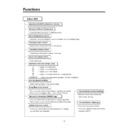
Functions
• Room temperature sensor. (THERMISTOR)
• Maintains the room temperature in accordance with the Setting Temp.
• Indoor fan is delayed for 5 sec at the starting.
• Restarting is inhibited for approx. 3 minutes.
• High, Med, Low
--- Lights up in operation
--- Lights up in Sleep Mode
--- Lights up in Timer Mode
--- Lights up in Deice Mode (for Heating Model)
OUTDOOR --- Lights up in compressor operation (for Cooling Model)
• Intermittent operation of fan at low speed.
• The fan is switched to low(Cooling), med(Heating) speed.
• The unit will be stopped after 1, 2, 3, 4, 5, 6, 7 hours.
• The unit will be stopped after 1, 2, 3, 4, 5, 6, 7 hours.
• The fan is switched to intermittent or irregular operation
• The fan speed is automatically switched from high to low speed.
• The fan speed is automatically switched from high to low speed.
• The louver can be set at the desired position or swing
up and down automatically.
Indoor Unit
Operation ON/OFF by Remote controller
Sensing the Room Temperature
Room temperature control
Starting Current Control
Time Delay Safety Control
Indoor Fan Speed Control
Operation indication Lamps (LED)
Soft Dry Operation Mode
• Both the indoor and outdoor fan
stops during deicing.
• The indoor fan stops until the
evaporator piping temperature will be
reached at 28°C.
Sleep Mode Auto Control
Natural Air Control by CHAOS Logic
Airflow Direction Control
Deice (defrost) control (Heating)
Hot-start Control (Heating)
- 4 -
Healthy Dehumidification Operation Mode.( )
Remote Control
Operation ON/OFF
Reset
Operation Mode Selection
Temperature Setting
Timer Selection
Timer Setting
JET COOL
Timer Cancel
Sleep Operation
Airflow Direction Control
(Cooling
model only)
(Heating
model only)
TEMPERATURE
LOW
HIGH
Cooling Operation Mode.( )
Heating Operation Mode.( )
Auto Operation Mode.( )
Fan Operation Mode
Horizontal Airflow Direction Control Button(Option)
Room, Temperature Display
Setting the Time or Timer
PLASMA(Option)/NEGATIVE ION(Option)
ON
OFF
SET
PLASMA
CANCEL
Fan Speed Selection
(Low)
(Med)
(High)
(CHAOS)
: (High:39°C
Low:11°C)
: OFF, ON, OFF ON
: Cancel Sleep Mode, Timer ON or Timer OFF
: 1, 2, 3, 4, 5, 6, 7, Off Timer
: Fan Operates without cooling or heating.
Cooling
Down to 18°C
Up to 30°C
Up to 30°C
Heating
Down to 16°C
Up to 30°C
Up to 30°C
- 24 -
Installation
Read completely, then follow step by step.
1. Installation of Indoor, Outdoor unit
1) Select the best location
1. Indoor unit
■
Do not have any heat or steam near the unit.
■
Select a place where there are no obstacles in
front of the unit.
front of the unit.
■
Make sure that condensation drainage can be
conveniently routed away.
conveniently routed away.
■
Do not install near a doorway.
■
Ensure that the space around the left and right of
the unit is more than 5cm. The unit should be
installed as high on the wall as possible, allowing
a minimum of 5cm from ceiling.
the unit is more than 5cm. The unit should be
installed as high on the wall as possible, allowing
a minimum of 5cm from ceiling.
■
Use a stud finder to locate studs to prevent
unnecessary damage to the wall.
unnecessary damage to the wall.
2. Outdoor unit
■
If an awning is built over the unit to prevent direct
sunlight or rain exposure, make sure that heat
radiation from the condenser is not restricted.
sunlight or rain exposure, make sure that heat
radiation from the condenser is not restricted.
■
Ensure that the space around the back and sides
is more than 10cm. The front of the unit should
have more than 70cm of space.
is more than 10cm. The front of the unit should
have more than 70cm of space.
■
Do not place animals and plants in the path of the
warm air.
warm air.
■
Take the air conditioner weight into account and
select a place where noise and vibration are mini-
mum.
select a place where noise and vibration are mini-
mum.
■
Select a place so that the warm air and noise
from the air conditioner do not disturb neighbors.
from the air conditioner do not disturb neighbors.
■
Rooftop Installations:
If the outdoor unit is installed on a roof structure,
be sure to level the unit. Ensure the roof structure
and anchoring method are adequate for the unit
location. Consult local codes regarding rooftop
mounting.
If the outdoor unit is installed on a roof structure,
be sure to level the unit. Ensure the roof structure
and anchoring method are adequate for the unit
location. Consult local codes regarding rooftop
mounting.
2) Piping length and elevation
More than 5cm
More than 5cm
More than 2.3m
More than 5cm
More than 10cm
More than 10cm
More
than 60cm
than 60cm
More than 60cm
More than 70cm
In case more than 5m
• Capacity is based on standard length and maximum
allowance length is on the basis of reliability.
• Oil trap should be installed every 5~7 meters.
Outdoor unit
Indoor unit
A
B
A
Oil trap
Outdoor unit
Indoor unit
B
CAUTION
Install the indoor unit on the wall where the height
from the floors more than 2.3 meters.
from the floors more than 2.3 meters.
CAUTION
24K(60Hz) 5/8"
1/4"
5
15
30
30
18K(50Hz) 1/2"
1/4"
5
15
30
30
24K(50Hz) 5/8"
3/8"
5
15
30
30
26K(50Hz) 5/8"
3/8"
5
15
30
30
Pipe Size
Capacity
(Btu/h)
GAS
LIQUID
Max.
length
A
(m)
Additional
Refrigerant
(g/m)
Max.
Elevation
B
(m)
Standard
Length
(m)
- 33 -
2) Form the piping
1. Form the piping by wrapping the connecting por-
tion of the indoor unit with insulation material and
secure it with two kinds of vinyl tapes.
secure it with two kinds of vinyl tapes.
If you want to connect an additional drain hose,
the end of the drain outlet should be routed
above the ground. Secure the drain hose appro-
priately.
the end of the drain outlet should be routed
above the ground. Secure the drain hose appro-
priately.
2. In cases where the outdoor unit is installed below
the indoor unit perform the following.
Tape the piping, drain
hose and connecting
cable from down to up.
Secure the tapped
piping along the
exterior wall using
saddle or equivalent.
hose and connecting
cable from down to up.
Secure the tapped
piping along the
exterior wall using
saddle or equivalent.
Taping
Drain
hose
hose
Pipings
Connecting
cable
cable
;
;
Trap is required to prevent water
from entering into electrical parts.
from entering into electrical parts.
Seal small openings
around pipings with a
gum type sealer.
around pipings with a
gum type sealer.
3. In cases where the Outdoor unit is installed above
the Indoor unit perform the following.
Tape the piping and connecting cable from down
to up.
Secure the taped piping along the exterior wall.
Form a trap to prevent water entering the room.
Fix the piping onto the wall by saddle or equiva-
lent.
to up.
Secure the taped piping along the exterior wall.
Form a trap to prevent water entering the room.
Fix the piping onto the wall by saddle or equiva-
lent.
;
;
Seal a small opening
around the pipings
with gum type sealer.
around the pipings
with gum type sealer.
Trap
Trap
1) Checking the drainage
1. To remove the front panel from the indoor unit,
remove the front panel from the indoor unit cabi-
net.
net.
Set the air direction louvers up-and-down to the
position(horizontally) by hand.
Remove the securing screws that retain the front
panel. Pull the lower left and right sides of the
grille toward you and lift it off.
position(horizontally) by hand.
Remove the securing screws that retain the front
panel. Pull the lower left and right sides of the
grille toward you and lift it off.
Pull the right and
the left side.
the left side.
Screw
2. To check the drainage.
Pour a glass of water
on the evaporator.
Ensure the water flows
through the drain hose
of the indoor unit with-
out any leakage and
goes out the drain exit.
on the evaporator.
Ensure the water flows
through the drain hose
of the indoor unit with-
out any leakage and
goes out the drain exit.
3. Drain piping
The drain hose should point downward for easy
drain flow.
drain flow.
Do not make drain piping.
Downward slope
Do not raise
Accumulated
drain water
drain water
Tip of drain hose
dipped in water
dipped in water
Air
Waving
Water
leakage
leakage
Water
leakage
leakage
Ditch
Less than
50mm gap
50mm gap
Water
leakage
leakage
4. Checking the Drainage and Forming the Pipings


