JBL DA 3504 (serv.man14) Service Manual ▷ View online
DA 3504
4/3/2 CHANNEL
AUTOMOTIVE
POWER AMPLIFIER
AUTOMOTIVE
POWER AMPLIFIER
TECHNICAL MANUAL
JBL CONSUMER PRODUCTS.INC.
250 CROSSWAYS PARK DRIVE
WOODBURY, N.Y. 11797
1-800-336-4JBL IN THE USA
250 CROSSWAYS PARK DRIVE
WOODBURY, N.Y. 11797
1-800-336-4JBL IN THE USA
H A Harman International Company
Part No.:1112-DA1002 Rev A
Part No.:1112-DA1002 Rev A
D E C A D E
SPECIFICATIONS
Specifications .........................................................1
Features .................................................................2
Test Conditions and Notes ......................................2
Controls and Connections .....................................3
Mounting the Amplifier............................................3
Typical System Configuration (Wiring) ....................4
Printed Circuit Boards (Top View)...................5
Parts Lists...........................................................6~8
Integrated Circuit Diagrams......................................11
Transistor Diagrams................................................12
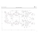
Schematic Diagrams...................
Transistor Diagrams................................................12
Schematic Diagrams...................
Block Diagrams.......................................................9
Packaging Exploded View........................................10
Packaging Exploded View........................................10
.......................13~15
Amplifier Exploded View...........................................16
Number of Channels . . . . . . . . . . . . . . . . . . .
4 Ohms Stereo . . . . . . . . . . . . . . . . . . . . . . .
2 Ohms Stereo . . . . . . . . . . . . . . . . . . . . . . .
4 Ohms Bridged . . . . . . . . . . . . . . . . . . . . . .
4 Ohms Bridged . . . . . . . . . . . . . . . . . . . . . .
T.H.D. @ 4 Ohms rated Power . . . . . . . . . . . . . . .
Frequency Response . . . . . . . . . . . . . . . . . . . .
Signal to Noise Ratio . . . . . . . . . . . . . . . . . . . .
Slew Rate. . . . . . . . . . . . . . . . . . . . . . . . . . . . . . . . . . . .
Channel Separation. . . . . . . . . . . . . . . . . . . . . . . . . . . . . . . .
Crossover Slope. . . . . . . . . . . . . . . . . . . . . . . . . . . . . . . . .
Fuse Size. . . . . . . . . . . . . . . . . . . . . . . . . . . . . . . . . . . . . . .
Line Level Sensitivity. . . . . . . . . . . . . . . . . . . . . . . . . . . . . . .
Speaker Level Sensitivity. . . . . . . . . . . . . . . . . . . . . . . . . . . . .
Speaker Level Sensitivity. . . . . . . . . . . . . . . . . . . . . . . . . . . . .
DC Operating Range. . . . . . . . . . . . . . . . . . . . . . . . . . . . . . ..
Length . . . . . . . . . . . . . . . . . . . . . . . . . . .
Width . . . . . . . . . . . . . . . . . . . . . . . . . . .
Depth . . . . . . . . . . . . . . . . . . . . . . . . . . .
Length . . . . . . . . . . . . . . . . . . . . . . . . . . .
Width . . . . . . . . . . . . . . . . . . . . . . . . . . .
Depth . . . . . . . . . . . . . . . . . . . . . . . . . . .
2,3,4
35Wx4
50Wx4
100Wx2
100Wx2
0.1%
20 Hz ~ 20K Hz(+1,-2dB)
90dB
>13V / us
>60dB
>100
12dB / oct
12dB / oct
250mV-4V
1V - 9V
9V - 18V
30 Amp ATC Type
11-7/8"
11-5/8"
2-9/16"
300mm
295mm
65mm
10.6lbs/4.8Kg.
External Dimensions (Inches)
External Dimensions (mms)
JBL continually strives to improve its products. New materials, production methods and design refinements are
introduced into existing models without notice as a routine expression of our design philosophy. For this reason,
DECADE Series Multichannel Automotive Amplifiers may differ in some respects from their published specifications
and descriptions, but will always equal or exceed the original specifications unless otherwise stated.
1
Multichannel Automotive Amplifier
DA 3504
Table of Contenrs
Damping Factor . . . . . . . . . . . . . . . . . . . . . . . . . . . . . . . . .
Weight . . . . . . . . . . . . . . . . . . . . . . . . . . .
Test Conditions and Notes
4-,3-, or 2-Channel Operation
Simultaneous Stereo +Mono Operation
Built-in optional 12dB/oct Low Pass Filter selectable to 70 or 100Hz
Simultaneous Stereo +Mono Operation
Built-in optional 12dB/oct Low Pass Filter selectable to 70 or 100Hz
Advanced MOSFET Oversized Floating Rail Power Supply
Floating Ground Factory - Head - Unit Speaker - Level input
Variable Input Sensitivity (250mV - 4V)
Fully Complementary Output Stage with Class-A Voltage Amplification
Gold-plated Power, Input and Output Connectors
2-Ohm Stable (Stereo)
Power-on Indicator Badge
All tests to be done, unless otherwise specified, from 20KHz to 20KHz at 14.4V DC into 4 ohm loads and adjust
the units gain so that with a .775 volt input signal the unit is at its maximum rated output. All measurements
will be done using an Audio precision system one and the supply voltage.
the units gain so that with a .775 volt input signal the unit is at its maximum rated output. All measurements
will be done using an Audio precision system one and the supply voltage.
An A+ line voltage of 14.4V DC shall be applied to the unit under test for all measurements unless otherwise
specified. The voltage applied to the unit shall be measured at the power connection on the Amplifier.
specified. The voltage applied to the unit shall be measured at the power connection on the Amplifier.
Signal Source
Unless otherwise specified, all tests shall be conducted with the Audio Signal Generator output configured to
be balanced, less than or equal to 50 ohm source impedance, and floating. The signal source "GND" shall be
connected to the Amplifier PWR GND at the Amplifier.
Unless otherwise specified, all tests shall be conducted with the Audio Signal Generator output configured to
be balanced, less than or equal to 50 ohm source impedance, and floating. The signal source "GND" shall be
connected to the Amplifier PWR GND at the Amplifier.
Output Load
Unless otherwise specified, all tests shall be conducted with 4 ohm resistive loads having less than 10%
reactive components at any frequency below 75KHz. Each resistor shall have a value that remains within 1%
while dissipating the rated output of the unit under test.
Unless otherwise specified, all tests shall be conducted with 4 ohm resistive loads having less than 10%
reactive components at any frequency below 75KHz. Each resistor shall have a value that remains within 1%
while dissipating the rated output of the unit under test.
Power Indicator LED steadily illuminates for normal operation. LED blinks when
protection circuitry is engaged, and during power up.
protection circuitry is engaged, and during power up.
2
Features
Multichannel Automotive Amplifier
DA 3504
Controls and Connections
Controls and Connections
Mounting the Amplifier
1. Preamp-Level Input Connector - Connects to
line-level output from the source unit
2. Speaker-Level Input Connector - Use this
connector for speaker level input signals.
A wire harness is supplied use with this
connectro. See"Typical System Configuration"
Section (page4)for wiring instructions
3. Speaker Output Connector - Connect speaker
3. Speaker Output Connector - Connect speaker
wiring to these connectors. See wiring instruc-
tions on page 4 for more information.
4. Fuse - 30 Amp attached type fuses.
4. Fuse - 30 Amp attached type fuses.
The JBL Decade Series amplifiers can be mounted in virtually any location inside the vehicle.
However, make sure to keep the amplifier away from heater vents or ducts.
However, make sure to keep the amplifier away from heater vents or ducts.
1. At the chosen site, use the amplifier as a mounting template and mark the locations of the
four mounting holes.
four mounting holes.
2. Drill a small pilot hole at each marked location.
3. Mount the amplifier and securely tighten the mounting screws.
5. Power Connection for 12v+,GND and REM
connections for power wires. See wiring
connections for power wires. See wiring
Instructions on page 4 for more information.
6. Input-Level Control - Adjusts input sensitivity for pre
amp level and speaker level inputs.
amp level and speaker level inputs.
7. Crossover Selector - Determines wheth the
crossover is a High-pass filter @120HZ(HP),a
Low-pass filter,@80Hz(LP) or unfiltered (FLAT)
crossover is a High-pass filter @120HZ(HP),a
Low-pass filter,@80Hz(LP) or unfiltered (FLAT)
8. Bass E.Q. - This switch activates a built-in Bass
Boost circuit used to increase low-bass output
on the selected soeaker output group. Enables
bass boost +6dB@50Hz
9. ST,or Stereo mode for normal operation
MO,or Mono mode for bridge operation.
Boost circuit used to increase low-bass output
on the selected soeaker output group. Enables
bass boost +6dB@50Hz
9. ST,or Stereo mode for normal operation
MO,or Mono mode for bridge operation.
3
Multichannel Automotive Amplifier
DA 3504
2
8
1
2
4
5
3
2
1
11
6
7
6
9

