JBL MEDIA 3 Service Manual ▷ View online
JBL Consumer Products Inc.
80 Crossways Park West
Woodbury, N.Y. 11797
1-800-336-4JBL in the USA
80 Crossways Park West
Woodbury, N.Y. 11797
1-800-336-4JBL in the USA
A Harman International Company
Part No.: MEDIA3SM Rev A
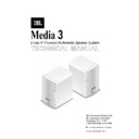
Media 3
TECHNICAL MANUAL
2-way 4" Powered Multimedia Speaker System
1
Two-way Powered Speaker System
Media 3
TABLE OF CONTENTS
Features..........................................................................1
Specifications .................................................................1
Disassembly Procedures................................................2
Media 3 Master Speaker Exploded View .....................3
Media 3 Slave Speaker Exploded View ........................4
Trouble Shooting ............................................................5
Block Diagram ................................................................6
Printed Circuit Boards ....................................................7
Electrical Parts Lists.......................................................9
Packaging Exploded View & Parts List .......................10
Integrated Circuit Diagrams .........................................11
Schematic Diagram .....................................................12
FEATURES
n
Two-way speaker system.
n
14 watt stereo amplifier.
n
Auto turn-on / turn off circuitry.
n
Magnetically shielded speakers for flicker-free use near
computer monitors.
computer monitors.
n
Dual stereo inputs.
n
Separate bass and treble controls.
n
Subwoofer output.
n
Stereo headphone output.
n
Built-in electronic equalization for proper frequency
balance with satellite speakers.
balance with satellite speakers.
SPECIFICATIONS
Speaker System.
.
.
.
.
.
.
.
.
.
.
Full range, two-way system
Speaker Size:
.
.
.
.
.
.
.
.
.
.
.
4” woofer and 1.5” tweeter
Total Amplifier Output Power: .
.
.
.
.
.
14W at less than 10% THD
Frequency Response: .
.
.
.
.
.
.
.
.
90Hz - 20kHz
Input Impedance
.
.
.
.
.
.
.
.
.
.
50k ohms
Headphone Output Jack .
.
.
.
.
.
.
.
Stereo miniplug (1/8”)
Subwoofer Output Jack: .
.
.
.
.
.
.
.
Stereo miniplug (1/8”)
Signal Input Jacks: .
.
.
.
.
.
.
.
.
.
Stereo miniplug (1/8”)
External Dimensions:
Height .
Height .
.
.
.
.
.
.
.
.
.
.
.
.
.
8.25”
Width .
.
.
.
.
.
.
.
.
.
.
.
.
.
5.5”
Depth .
.
.
.
.
.
.
.
.
.
.
.
.
.
4.9”
Weight .
.
.
.
.
.
.
.
.
.
.
.
.
.
9.75 lbs. per pair
External Dimensions (metric)
Height .
Height .
.
.
.
.
.
.
.
.
.
.
.
.
.
210mm
Width .
.
.
.
.
.
.
.
.
.
.
.
.
.
140mm
Depth .
.
.
.
.
.
.
.
.
.
.
.
.
.
124mm
Weight:.
.
.
.
.
.
.
.
.
.
.
.
.
.
4.4 kgs per pair
2
Two-way Powered Speaker System
Media 3
Please refer to the explosion drawing, the disassembly
procedures are as follows:
procedures are as follows:
For Master Speaker
Step 1
Unscrew 6 M3.5x15 screws (36) from rear panel (35).
Separate the Front and Rear Panels (8) (35).
Separate the Front and Rear Panels (8) (35).
Step 2
To disassemble the Heat-sink (31) from IC PCB (25)
unscrew 4 M3x8 (33) screws from Rear Panel.
unscrew 4 M3x8 (33) screws from Rear Panel.
Disassemblingthe Heat-sink
Unscrew 2 M3x12 (26) screws from the IC PCB (25).
Unscrew 4 M3x5 ISO screws (33) of IC PCB (25).
Unscrew 4 M3x5 ISO screws (32) from Heat-sink (31).
Hexagon bronze stick between Heat-sink and IC PCB (25)
will be loosened at the same time.
Hexagon bronze stick between Heat-sink and IC PCB (25)
will be loosened at the same time.
Step 3 (RCA PCB(28)
Unscrew 2 M3x8 screw (30) on Rear Panel, then take out
the RCA bracket. The RCA PCB (28) can be separated
from the shell also.
the RCA bracket. The RCA PCB (28) can be separated
from the shell also.
Step 4 (Front Panel)
To disassemble VR PCB (22) remove 3 VR knobs (6).
Unscrew 2 M3x6 screws (21).
Unscrew 2 M3x6 screws (21).
Remove VR PCB (22).
Loosen 3 internal caps (20).
To disassemble the LED PCB (17) unscrew M3x8 (18).
To disassemble the SW PCB (16) unscrew 2 M3x8 (14)
screws on Rear Panel.
screws on Rear Panel.
To disassemble the Earphone PCB (9) unscrew 2 M3x8
(11) screws on the Front Panel. Remove the bracket (10)
and Earphone PCB (9).
(11) screws on the Front Panel. Remove the bracket (10)
and Earphone PCB (9).
To disassemble the 1 ¾” Speaker (23) unscrew 2 M3.5x13
screws (24) from the internal side of the Front Panel.
screws (24) from the internal side of the Front Panel.
To disassemble the 4” Speaker remove the metal grille (3)
and unscrew 4 M3.5x13(4) screws. The Speaker can then
be removed.
and unscrew 4 M3.5x13(4) screws. The Speaker can then
be removed.
The Slave Speaker
Step 1
Unscrew 6 M3.5x15 screws (36) and separate the Front
and Rear Panels (38) & (39).
and Rear Panels (38) & (39).
Step 2 (Rear Panel)
To Disassemble RCA PCB (28) unscrew 2 M3x8 screws
(30) from Rear Panel. Take out RCA bracket (29), then
RCA PCB (28) can be removed from sink.
(30) from Rear Panel. Take out RCA bracket (29), then
RCA PCB (28) can be removed from sink.
Step 3 (Front Panel)
To disassemble 1 ¾” speak (23) Unscrew 2 M3.5x13
screws (24).
screws (24).
To disassemble 4” speaker (5) remove the grille (15)
and remove 4 M3.5x13 screws (4). Then the speaker
can be removed.
and remove 4 M3.5x13 screws (4). Then the speaker
can be removed.
DISASSEMBLY PROCEDURES
3
Two-way Powered Speaker System
Media 3
MEDIA 3 MASTER EXPLODED VIEW
( with amplifier)

