JBL LS 120P EU Service Manual ▷ View online
Service Manual
Released EU2012
harman/kardon, Inc.
Rev 0, 02/2012
250 Crossways Park Dr.
Woodbury, New York, 11797
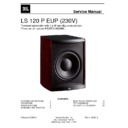
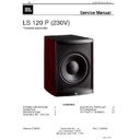
LS 120 P EUP (230V)
Powered subwoofer with 0,5 W standby consumption.
(From serial number ME2572-002088.)
(From serial number ME2572-002088.)
CONTENTS
SYSTEM CONNECTIONS
2
ELECTRICAL PARTS LIST
6
OPERATION
3
PCB DRAWINGS
11
SPECIFICATIONS
4
SCHEMATIC DIAGRAMS
15
ASSEMBLY INSTRUCTION
5
English
SYSTEM CONNECTIONS
If you have a Dolby
®
Digital or DTS
®
receiver/processor
with a low-frequency-effects (LFE) or subwoofer output:
5
If your receiver/processor does not contain a Dolby Digital
or DTS processor, but has subwoofer outputs:
or DTS processor, but has subwoofer outputs:
Set line-level/LFE switch to
“Normal.”
“Normal.”
NOTE: If your receiver/processor
has only one sub out, you may
use either the L or R input.
has only one sub out, you may
use either the L or R input.
Set LFE/Normal switch to “LFE.”
LS120P/230
LS120P/230
0012CSK - JBL LS120P OM UK v2.qxp:v 14/01/08 17:12 Side 5
JBL
LS 120P EuP/230 Service Manual
Page 2 of 25
POWER ON
Plug your subwoofer’s AC cord into a wall outlet. Do not use the
outlets on the back of the receiver.
Plug your subwoofer’s AC cord into a wall outlet. Do not use the
outlets on the back of the receiver.
Initially set the Subwoofer-Level Control
2 to the “min” position.
Turn on your sub by pressing the Power Switch
6 on the rear panel.
Turn on your entire audio system and start a CD or movie soundtrack
at a moderate level.
at a moderate level.
AUTO ON/STANDBY
With the Power Switch
With the Power Switch
6 in the ON position, the Status LED 4 on
back will remain lit in red or green to indicate the On/Standby mode
of the subwoofer.
of the subwoofer.
RED = STANDBY (no signal detected, Amp Off)
GREEN = ON (signal detected, Amp On)
The subwoofer will automatically enter the Standby mode after
approximately 10 minutes when no signal is detected from your
system. The subwoofer will then power ON instantly when a signal is
detected. During periods of normal use, the Power Switch
approximately 10 minutes when no signal is detected from your
system. The subwoofer will then power ON instantly when a signal is
detected. During periods of normal use, the Power Switch
6 can be
left on. You may turn off the Power Switch
6 for extended periods
of nonoperation, e.g., when you are away on vacation.
GETTING STARTED
Turn your Subwoofer-Level Control
Turn your Subwoofer-Level Control
2 up to the halfway position. If
no sound emanates from the subwoofer, check the AC-line cord and
input cables. Are the connectors on the cables making proper
contact? Is the AC plug connected to a “live” receptacle? Has the
Power Switch
input cables. Are the connectors on the cables making proper
contact? Is the AC plug connected to a “live” receptacle? Has the
Power Switch
6 been pressed to the “On” position? Once you have
confirmed that the subwoofer is active, proceed by playing a CD,
record or cassette. Use a selection that has ample bass information.
record or cassette. Use a selection that has ample bass information.
ADJUST LEVEL
Set the overall volume control of the preamplifier or stereo to a
comfortable level. Adjust the Subwoofer-Level Control
Set the overall volume control of the preamplifier or stereo to a
comfortable level. Adjust the Subwoofer-Level Control
2 until you
obtain a pleasing blend of bass. Bass response should not over -
power the room but rather be adjusted so there is a harmonious
blend across the entire musical range. Many users have a tendency
to set the subwoofer volume too loud, adhering to the belief that a
subwoofer is there to produce lots of bass. This is not entirely true.
A subwoofer is there to enhance bass, extending the response of the
entire system so the bass can be felt as well as heard. However,
overall balance must be maintained or the music will not sound
natural. An experienced listener will set the volume of the subwoofer
so its impact on bass response is always there but never obtrusive.
PHASE CONTROL
The Phase Switch
The Phase Switch
0 determines whether the subwoofer speaker’s
pistonlike action moves in and out with the main speakers, 0˚, or
opposite the main speakers, 180˚. Proper phase adjustment depends
on several variables such as room size, subwoofer placement and
listener position. Adjust the phase switch to maximize bass output at
the listening position.
opposite the main speakers, 180˚. Proper phase adjustment depends
on several variables such as room size, subwoofer placement and
listener position. Adjust the phase switch to maximize bass output at
the listening position.
CROSSOVER ADJUSTMENT
The Crossover Adjustment Control
The Crossover Adjustment Control
3 determines the highest
frequency at which the subwoofer reproduces sounds. If your main
speakers can comfortably reproduce some low-frequency sounds,
set this control to a lower frequency setting, between 50Hz and
100Hz. This will concentrate the subwoofer’s efforts on the ultradeep
bass sounds required by today’s films and music.
If you are using smaller bookshelf speakers that do not extend to the
lower bass frequencies, set the Crossover Adjustment control to a
higher setting, between 120Hz and 150Hz.
NOTE: This control will have no effect if the LFE/Normal Selector
1
is set to LFE. If you have a Dolby Digital or DTS processor/receiver,
the Low-Pass Frequency is set by the processor/receiver. Consult
your owner’s manual to learn how to view or change this setting.
the Low-Pass Frequency is set by the processor/receiver. Consult
your owner’s manual to learn how to view or change this setting.
The enclosure may be cleaned using a soft cloth to remove finger-
prints or to wipe off dust.
prints or to wipe off dust.
The grille may be gently vacuumed. Stains may be removed with an
aerosol cleaner, following its instructions. Do not use any solvents
on the grille.
aerosol cleaner, following its instructions. Do not use any solvents
on the grille.
All wiring connections should be inspected and cleaned or remade
periodically. The frequency of maintenance depends on the metals
involved in the connections, atmospheric conditions and other
factors, but once per year is the minimum.
periodically. The frequency of maintenance depends on the metals
involved in the connections, atmospheric conditions and other
factors, but once per year is the minimum.
In the event that your subwoofer ever needs service, contact your
local JBL dealer or distributor, or visit www.jbl.com for a service
center near you.
local JBL dealer or distributor, or visit www.jbl.com for a service
center near you.
OPERATION
6
MAINTENANCE AND SERVICE
0012CSK - JBL LS120P OM UK v2.qxp:v 14/01/08 17:12 Side 6
JBL
LS 120P EuP/230 Service Manual
Page 3 of 25
English
7
SPECIFICATIONS
LS 120P
Frequency Response
25Hz – 150Hz
Amplifier RMS Power
400 Watts
Amplifier Peak Dynamic Power
†
700 Watts
Crossover Frequency
50Hz – 150Hz;
24dB/octave, continuously adjustable
24dB/octave, continuously adjustable
Driver
300mm (12") PolyPlas
™
Dimensions (H x W x D)
487mm x 375mm x 425mm
(enclosed only)
(19-3/16" x 14-3/4" x 16-3/4")
Dimensions (H x W x D)
500mm x 375mm x 438mm
(with feet, controls, grille, etc.)
(19-11/16" x 14-3/4" x 17-1/4")
Weight
25.8kg (57 lb)
†
The Peak Dynamic Power is measured by recording the highest center-to-peak voltage
measured across the output of a resistive load equal to minimum impedance of the transducer,
using a 50Hz sine wave burst, 3 cycles on, 17 cycles off.
measured across the output of a resistive load equal to minimum impedance of the transducer,
using a 50Hz sine wave burst, 3 cycles on, 17 cycles off.
Declaration of Conformity
We, Harman Consumer Group, Inc.
2, route de Tours
72500 Château du Loir
France
72500 Château du Loir
France
declare in own responsibility that the product
described in this ownerʼs manual is in compliance
with technical standards:
EN 55013:2001+A1:2003
EN 55020:2002+A1:2003
EN 61000-3-2:2000
EN 61000-3-3:1995+A1:2001
EN 60065:2002
Laurent Rault
Harman Consumer Group, Inc.
Château du Loir, France 5/07
Declaration of Conformity
We, Harman Consumer Group, Inc.
2, route de Tours
72500 Château du Loir
France
72500 Château du Loir
France
declare in own responsibility that the product
described in this ownerʼs manual is in compliance
with technical standards:
EN 61000-6-3:2001
EN 61000-6-1:2001
Laurent Rault
Harman Consumer Group, Inc.
Château du Loir, France 5/07
0012CSK - JBL LS120P OM UK v2.qxp:v 14/01/08 17:12 Side 7
JBL
LS 120P EuP/230 Service Manual
Page 4 of 25


