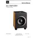
JBL ES150P Service Manual ▷ View online
Part Number
Description
Qty
241-100-05361-0RAE
Cabinet, cherry
1
241-100-05361-0BAE
Cabinet, black
1
241-100-05361-0YAE Cabinet,
beech
1
327-010-00622-E
BLACK Button
4
249-HPS-05178-0BAE
HIPS port tube
1
328-000-05496-0WAE
White damping material
1
244-100-05276-0BAE
Plastic grille with logo
1
403-000-05489-E
Paper board
1
25PR12FZL-DW04-E
10'' woofer
1
010-7620-05103-E
AMP
1
361-NYL-05101-0BAE
LED base
1
315-HPS-05097-0AAE
Logo base
1
316-HPS-05236-0AAE
Logo 1
352-KM03520D1148-E hex head screw,galvanized
φ3.5*L20 d=7mm
4
213-100-05156-0AAE
HIPS trim ring
1
352-KM04020D1149-E hex head screw,galvanized
φ4.0*L20 d=8mm
8
321-ABS-00008-E
Feet pole ,plastic parts
4
321-RUB-00009-E
Feet pole, rubber parts
4
352-HM04030D500-E
Screw t4*30
4
352-AM04020D880-E
Screw,
Φ4*L20 d=8mm
10
406-000-05610-E
OM
1
400-000-07836-E
Carton
1
MODEL NAME: ES150P/230
JBL ES 150P/230V
Service Manual
Page 5 of 30
ES150P Test Set Up and Procedure
Equipment needed:
• Function/signal
generator/sweep
generator
• Integrated
Amplifier
• Multimeter
• Speaker
cables
General Unit Function (UUT = Unit Under Test)
1) From the signal generator, connect line level (RCA) cables to the Subwoofer Line Level Input jacks L/R on
the UUT. Use a Y-cable from a mono source if necessary to connect to both inputs.
2) Turn the CROSSOVER control to maximum (150).
3) Turn the LEVEL control on the UUT to completely counterclockwise (MIN).
4) LFE/NORMAL switch should be in NORMAL position.
5) PHASE switch position does not matter.
6) Turn on generator; adjust to 75mV, 50 Hz.
7) Plug in UUT; turn the power switch ON. LED should switch from Red to Green.
8) Turn LEVEL control full clockwise (MAX); immediate and vigorous bass response should be heard and felt
from port tube opening on the bottom.
9) Turn off generator, turn LEVEL control full counterclockwise (MIN), and disconnect RCA cable.
Sweep Function
1) Follow steps 1-8 above, using a sweep generator as a signal source.
2) Sweep generator from 20Hz to 300Hz. Listen to the cabinet and drivers for any rattles, clicks, buzzes or
2) Sweep generator from 20Hz to 300Hz. Listen to the cabinet and drivers for any rattles, clicks, buzzes or
any other noises. If any unusual noises are heard, remove woofer and test.
Driver Function
1) Remove woofer from cabinet; detach + and - wire clips.
2) Check DC resistance of woofer; it should be 3.4 ohms ±10%
3) Connect a pair of speaker cables to driver terminals. Cables should be connected to an integrated amplifier
1) Remove woofer from cabinet; detach + and - wire clips.
2) Check DC resistance of woofer; it should be 3.4 ohms ±10%
3) Connect a pair of speaker cables to driver terminals. Cables should be connected to an integrated amplifier
fed by a signal generator. Turn on generator and adjust so that speaker level output is 5.0V.
4) Sweep generator from 20Hz to 1kHz. Listen to driver for any rubbing, buzzing, or other unusual noises.
ES150P
Service Manual
Page 6 of 30
ES150P
JBL ES 150P/230V
Service Manual
Page 7 of 30
JBL ES 150P/230V
Service Manual
Page 8 of 30
Click on the first or last page to see other ES150P service manuals if exist.

