Harman Kardon FL 8550 (serv.man4) Service Manual / Technical Bulletin ▷ View online
harman/kardon
Service Bulletin
Service bulletin # 2001-001 JANUARY
2001
To:
All harman/kardon Service Centers
Models: FL8350, 8550
Subject: Carousel Diode failure,
In the event you receive an FL8350 with the complaint “The carousel turns continuously,” or “ the unit does not stop at
the selected CD”. Perform the following modification.
This modification should be carried out systematically if Diode D3 (P/N 3100-800000-000) needs to be changed.
Part required: FL8350 Repair kit;
the selected CD”. Perform the following modification.
This modification should be carried out systematically if Diode D3 (P/N 3100-800000-000) needs to be changed.
Part required: FL8350 Repair kit;
Part Number FLREPKITCARR
The kit is composed of the following parts.
1Pcs.
Cap 10 uF; Resistance 220K ohm; Fet BS170; Emitting diode D3 (P/N 3100-800000-000)
2 Pcs. Diode 1N4148
Disassembly procedure.
Remove the top cover.
Remove the 2 cabinet holders, and the 2 metal frame holders.
Unscrew the front panel and pull it forwards.
Place the loading table in a vertical position.
Place the loading table in a vertical position.
Disconnect and remove the Diode PCB.
Modification.
1. Exchange the Diode D3. (Remember to place the new diode in the correct sense) See Picture Page 2
2. Cut and clean the track leading to R2. (See picture Page 3)
3. Remove the resistor R2. (See picture Page 2) and replace it on the track prepared in the previous step.
(See Picture Page 3)
4. The N-Fet transistor can now be placed in the original position of R2. Bend outwards the middle leg of
the transistor as illustrated in Page 3.
5. Mount the two 1N4148 Diodes between the carousel motor legs and the middle leg of the transistor as
shown in the Picture Page 4.
6. Mount the 10 uF Capacitor between ground and the middle leg of the transistor (see Picture Page 4)
7. Mount the 220k ohm resistor between ground and the middle leg of the transistor. (see Picture Page 4)
8. Reconnect the PCB and reassemble the unit in reverse order, following the instructions above.
9. Test the unit, the Diode D3 now transmits only when the carousel is turning.
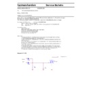
Diagram for FL 8350.
Carrousel
Motor
LED Diode Res. R2
R1
220k
220k
+
C2
10uF
10uF
U2
BS170/TO
BS170/TO
1
2
3
D2
1N4148
D3
1N4148
FL 8350
Page 2.
PCB from underside of the carrousel.
Remember to exchange the DIODE D3. Part no. 3100-800000-000.
Remember to mount the new diode the right way.
Remember to mount the new diode the right way.
Exchange D3
The modification is in this area.
Ground
+ 5 volt
carrousel motor
carrousel motor
R2
FL
8350
Page 3.
Remove R2
Cut here, clean and put on some solder.
Place R2 here.
Place the N-Fet transistor where the R2 was mounted originally.
Bend out the leg in the middle, as showed at the picture.
Flat side of the
transistor
transistor
FL
8350
Page 4.
Mount the 2 pcs. Of 1N4148 diodes as showed.
Carrousel motor legs.
Mount the cap. 10uF from ground to middle leg of the FET.
Mount the resistor 220k ohm from ground to middle leg of the FET.
Ground.
Mount the PCB again, and test it.
Now the diode D3 is only transmitting when the carrousel turns
Now the diode D3 is only transmitting when the carrousel turns
Cathode
Display

