Harman Kardon AVR 5550 (serv.man14) Service Tips ▷ View online
The Technical Team
Harman Consumer Group International 2 route de Tours 72500 Château du Loir FRANCE
pin 32.FAN1-OUT for
the Heat detection
the Heat detection
pin 33.FAN2-OUT for
the Level detection
the Level detection
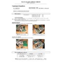
AVR4550/5550 Quick Description on:
FANS CONTROL
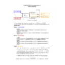
Secondary Block Diagram
The Fans depend of the heat and of the audio level on AVR4550 and AVR5550.
IC12 (DSP board) activate fans with a feedback of measures (the Level detection and the
Heat detection).
Mesure 1 :
Level detection :
Location:
-
It takes the measure on N806 on MAIN board. The level measure goes to IC12 pin
34.FANCONT on DSP board.
Voltage:
34.FANCONT on DSP board.
Voltage:
-
The control of fans starts from > 2V4 pin 1 of N400 (DSP board), then it stops when the
voltage is < 2V4
voltage is < 2V4
Mesure 2 :
Heat detection :
Location:
-
It takes the measure from POSISTOR IN P071 and from POSISTOR IN P052. The Heat
measure goes to IC12 pin 30.FAN1-IN and IC12 pin 31.FAN2-IN on DSP board.
Voltage:
measure goes to IC12 pin 30.FAN1-IN and IC12 pin 31.FAN2-IN on DSP board.
Voltage:
-
Start from > 1.80V pin 15 (4-CH THERMAL IN) of P811 (MAIN board) and stops from
<1.04V
<1.04V
-
Start from > 1.80V pin 14 (3-CH THERMAL IN) of P811 (MAIN board) and stops from
<1.04V
<1.04V
Control :
Fans Control :
-
In both case (Heat detection active or Level detection active) Fan 1 and Fan 2 start always
at the same time due to the CNT B’D with 2 diodes (see
at the same time due to the CNT B’D with 2 diodes (see
Secondary Block Diagram).
-
Pin 12 of P811 (FRONT FAN OUT) is for the Heat detection (pin 32.FAN1-OUT of IC12).
Fans are activated when pin 32 is active at 3V
Fans are activated when pin 32 is active at 3V
-
Pin 13 of P811 (REAR FAN OUT) is for the Level detection (pin 33.FAN2-OUT of IC12).
Fans are activated when pin 33 is active at 3V
Fans are activated when pin 33 is active at 3V
-
On MAIN board Q601 turns on fan 1 or front fan and Q602 turns on fan 2 or rear fan.
IC12
DSP board
DSP board
Level detection
Heat detection
Motor Front fan 1
Motor Rear fan 2
CNT B’D
OUT LEVEL DET from
MAIN b'd N400 P811 pin19
OUT LEVEL DET to DSP board N400 pin 1
HEAT DETECTION from
3CH AMP board P307
HEAT DETECTION to DSP
board N400 pin 14-15
HEAT DETECTION to MAIN board N808
Display

