Harman Kardon AVR 500 (serv.man14) Service Manual / Technical Bulletin ▷ View online
harman/kardon Incorporated 250 Crossways Park Drive, Woodbury New York 11797 (516) 496-3400
harman/kardon
Service Bulletin
Service bulletin # H/K2000-04 November 2000
Warranty labor rate:
AVR500
MAJOR
repair
To:
All harman/kardon Service Centers
AVR7000
MINOR repair
Models: AVR500/AVR7000
Subject: Noise in Logic 7 Mode
In the event you receive an AVR500 or AVR7000 receiver with the complaint “There is crackling, noise,
or distortion coming from my loudspeakers when my receiver is in the Logic 7 mode with certain
program material playing”, perform the following procedure:
AVR500 ONLY: REMOVAL AND MODIFICATION OF THE DSP BOARD (replace IC709 TRAD ROM-0001)
WARNING: FOLLOW PROPER STATIC CONTROL PROCEDURES and use caution during the removal of the
DSP board, and during installation of new IC709 to prevent damage.
1) Remove the top cover, (14) Black Phillips screws at the sides and rear of the unit.
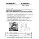
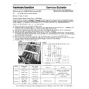
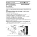
2) Locate the DSP PC Board; Figure 1. Remove the two metal braces at the top of the unit. If necessary, cut
the cable ties attached to the braces to move any wires away from the area.
3) Pull the white 22 conductor ribbon cable at the rear of the DSP PC Board straight out of its receptacle.
4) Unplug the white 5 conductor molex cable at the top of the DSP PC Board.
5) Remove the (33) plated Phillips screws on the left side of the rear backplate; see Figure 2. Do not remove
4) Unplug the white 5 conductor molex cable at the top of the DSP PC Board.
5) Remove the (33) plated Phillips screws on the left side of the rear backplate; see Figure 2. Do not remove
any additional screws on the right side. If using a power tool, use care and minimum effort to avoid
damaging the various plastic receptacles.
damaging the various plastic receptacles.
6) Remove all three black plastic plugs that cover the optical inputs at the rear of the DSP PC Board.
7) Pull on the left side of the rear backplate, away from the receiver chassis; you should be able to pull it away
7) Pull on the left side of the rear backplate, away from the receiver chassis; you should be able to pull it away
enough to allow the DSP PC Board to be pulled straight up and out of the receiver.
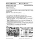
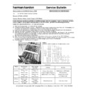
8) Unsolder IC709 TRAD ROM-0001 and replace with hk part# J21310030011. See illustration on following
page for location on PCB.
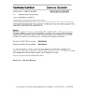
Model Serial
Number
120V
Serial Number
230V RDS
STATUS
ACTION
AVR500
TH0002-01000
To
TH0002-14977
TH0006-01000
To
TH0006-05105
Noise in Logic 7 Mode
Replace IC709
TRAD ROM-0001
AVR500
TH0002-14978 or
higher
TH0006-05106 or
higher
Modified by factory
NONE REQUIRED
harman/kardon Incorporated 250 Crossways Park Drive, Woodbury New York 11797 (516) 496-3400
Location of IC upgrade for the AVR500/AVR7000:
9) Replace DSP PC Board back into its (3) receptacle plugs atop the MAIN PCB.
10) Replace all screws, braces, and any cable ties that were cut during disassembly. Before tightening the
10) Replace all screws, braces, and any cable ties that were cut during disassembly. Before tightening the
screws, make sure all PCB’s and their RCA jacks are firmly seated in their respective holes in the rear
backplate. If using a power tool, use care and minimum effort to avoid damaging the various plastic
receptacles.
backplate. If using a power tool, use care and minimum effort to avoid damaging the various plastic
receptacles.
11) Plug both the 22 conductor ribbon cable and the 5 conductor molex cable back into their receptacles.
12) Replace the top cover and optical plugs.
13) Test unit by powering up the receiver and playing a music source in the Logic 7 mode.
AVR7000 ONLY: MODIFICATION OF THE DSP BOARD (replace IC101 AT27LV020A)
12) Replace the top cover and optical plugs.
13) Test unit by powering up the receiver and playing a music source in the Logic 7 mode.
AVR7000 ONLY: MODIFICATION OF THE DSP BOARD (replace IC101 AT27LV020A)
WARNING: FOLLOW PROPER STATIC CONTROL PROCEDURES and use caution during the installation of
new IC101 to prevent damage.
1) Remove the top cover, (16) Black Phillips screws at the sides and rear of the unit.
2) Locate the DSP PC Board and IC101 with the illustrations above.
3) Unsolder IC101 AT27LV020A and replace with hk part# J2131328001X. See illustration above for location
on PCB.
4) Replace top cover and all Phillips screws.
5) Test unit by powering up the receiver and playing a music source in the Logic 7 mode.
5) Test unit by powering up the receiver and playing a music source in the Logic 7 mode.
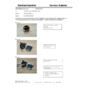
Model Serial
Number
120V
Serial Number
230V RDS
STATUS
ACTION
AVR7000
TH0003-01000
To
TH0003-05222
Modified by factory
Noise in Logic 7 Mode
Replace IC101
AT27LV020A
AVR7000
TH0003-05223
Or higher
Modified by factory
Modified by factory
NONE REQUIRED
Display

