Harman Kardon AVR 370 (serv.man7) Service Manual / Technical Bulletin ▷ View online
harman/kardon
Service Bulletin
AVR 270 + AVR 370
June 2014
Service bulletin # HK2013‐002_Version 2!
To:
All Harman Kardon Service Centers.
Models:
AVR270/230 and AVR 370/230
Subject:
Mechanical noise from power supply / High pinch tone from power supply PCB.
Mechanical noise from power supply:
In the event you receive a unit for repair with the complaint: Mechanical noise from power supply ‐ Check and
replace the PFC inductor, pos 40 in exploded view (part number: CLZ9Z148Z).
Procedure:
In the event you receive a unit for repair with the complaint: Mechanical noise from power supply ‐ Check and
replace the PFC inductor, pos 40 in exploded view (part number: CLZ9Z148Z).
Procedure:
Remove (13) top cover screws: There are (3) on each side and (7) on the back.
Remove the top cover.
Disconnect the PFC inductor from CN91 on the power supply.
Locate the PFC inductor, remove (2) screws and remove the inductor.
Mount the new PFC inductor and reconnect to CN91.
Reassemble unit.
Test the unit.
Remove the top cover.
Disconnect the PFC inductor from CN91 on the power supply.
Locate the PFC inductor, remove (2) screws and remove the inductor.
Mount the new PFC inductor and reconnect to CN91.
Reassemble unit.
Test the unit.
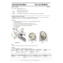
Exploded view
Old
New
Time:
This repair is rated as a 1 hour repair time, max. if no other repairs are made.
IRIS code:
Use the below IRIS codes when reporting this service repair:
Conditions
Symptoms
Section (Area) Defect (cause)
Repair (Remedy)
Position
IRIS CODES:
2 (1)
Intermittently
(Constantly)
Intermittently
(Constantly)
145
Noisy
component(s)
Noisy
component(s)
PSU
Power supply
Power supply
N
Defective electrical
component /
module
Defective electrical
component /
module
A
Replacement
Replacement
pos 40
Model
Serial number
Status
Action
PN used
AVR270/370
All
Mechanical noise from power
supply.
supply.
Exchange PFC inductor.
CLZ9Z148Z
harman/kardon
Service Bulletin
AVR 270 + AVR 370
June 2014
High pinch tone from SMPS power supply PCB:
In the event you receive a unit for repair with the complaint: High pinch tone from SMPS power supply PCB ‐ Check
and replace capacitors C983 and C984 1kV/470pF/K placed on SMPS power supply board (Part number:
CCKT3A471KB)
Procedure:
In the event you receive a unit for repair with the complaint: High pinch tone from SMPS power supply PCB ‐ Check
and replace capacitors C983 and C984 1kV/470pF/K placed on SMPS power supply board (Part number:
CCKT3A471KB)
Procedure:
Remove (13) top cover screws: There are (3) on each side and (7) on the back.
Remove the top cover.
Locate and remove the PFC inductor (see above)
Locate the SMPS PCB. Remove (5) screws.
Remove connectors CN20, CN90, SW91, SW92 and CN66.
Remove connections to BN65 and BN67
Remove the top cover.
Locate and remove the PFC inductor (see above)
Locate the SMPS PCB. Remove (5) screws.
Remove connectors CN20, CN90, SW91, SW92 and CN66.
Remove connections to BN65 and BN67
Remove the SMPS PCB from the AVR.
Locate and replace capacitors C983 and C984
Reassemble unit.
Test the unit.
Locate and replace capacitors C983 and C984
Reassemble unit.
Test the unit.
IRIS code:
Use the below IRIS codes when reporting this service repair:
Use the below IRIS codes when reporting this service repair:
Conditions
Symptoms
Section (Area) Defect (cause)
Repair (Remedy)
Position
IRIS CODES:
2 (1)
Intermittently
(Constantly)
Intermittently
(Constantly)
145
Noisy
component(s)
Noisy
component(s)
PSU
Power supply
Power supply
N
Defective electrical
component /
module
Defective electrical
component /
module
A
Replacement
Replacement
C983, C984
Model
Serial number
Status
Action
PN used
AVR270/370
All
High pinch tone from power supply.
Exchange C983, C984
CCKT3A471KB
Screw
Display

