Harman Kardon AVR 2550 (serv.man6) Service Manual ▷ View online
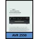
AVR 2 5 5 0 Audio/VideoReceiver
Service Manual
AVR 2550
Power for the Digital Revolution
™
®
TECHNICAL SPECIFICATIONS
Technical Specifications
Audio Section
Stereo Mode
Continuous Average Power (FTC)
Stereo Mode
Continuous Average Power (FTC)
50 Watts per channel, 20Hz–20kHz,
@ < 0.07% THD, both channels driven into 8 ohms
@ < 0.07% THD, both channels driven into 8 ohms
Five-Channel Surround Modes
Power Per Individual Channel
Power Per Individual Channel
Front L&R channels:
40 Watts per channel,
@ < 0.07% THD, 20Hz–20kHz into 8 ohms
40 Watts per channel,
@ < 0.07% THD, 20Hz–20kHz into 8 ohms
Center channel:
40 Watts, @ < 0.07% THD, 20Hz–20kHz into 8 ohms
40 Watts, @ < 0.07% THD, 20Hz–20kHz into 8 ohms
Surround channels:
40 Watts per channel,
@ < 0.07% THD, 20Hz–20kHz into 8 ohms
40 Watts per channel,
@ < 0.07% THD, 20Hz–20kHz into 8 ohms
Input Sensitivity/Impedance
Linear (High Level)
200mV/47kohms
Signal-to-Noise Ratio (IHF-A)
95dB
Surround System Adjacent Channel Separation
Analog Decoding
40dB
(Pro Logic, etc.)
Dolby Digital (AC-3)
Dolby Digital (AC-3)
55dB
DTS
55dB
Frequency Response
@ 1W (+0dB, –3dB)
10Hz–100kHz
High Instantaneous
Current Capability (HCC)
Current Capability (HCC)
±25 Amps
Transient Intermodulation
Distortion (TIM)
Distortion (TIM)
Unmeasurable
Rise Time
16 µsec
Slew Rate
40V/µsec
FM Tuner Section
Frequency Range
87.5–108MHz
Usable Sensitivity
IHF 1.3 µV/13.2dBf
Signal-to-Noise Ratio
Mono/Stereo: 70/65dB (DIN)
Distortion
Mono/Stereo: 0.15/0.3%
Stereo Separation
35dB @ 1kHz
Selectivity
±300kHz: 65dB
Image Rejection
80dB
IF Rejection
90dB
AM Tuner Section
Frequency Range
522–1620kHz
Signal-to-Noise Ratio
45dB
Usable Sensitivity
Loop: 500µV
Distortion
1kHz, 50% Mod: 0.8%
Selectivity
±9kHz: 30dB
Video Section
Video Format
PAL/NTSC
Input Level/Impedance
1Vp-p/75 ohms
Output Level/Impedance 1Vp-p/75 ohms
Video Frequency
Response
Video Frequency
Response
10Hz–8MHz (–3dB)
General
Power Requirement
AC 220-240V/50Hz
Power Consumption
72W idle, 580W maximum
(2 channels driven)
(2 channels driven)
Dimensions (Max)
Width
440mm
Height
166mm
Depth
365mm
Weight
10.6 kg
Depth measurement includes knobs, buttons and terminal connections.
Height measurement includes feet and chassis.
All features and specifications are subject to change without notice.
Height measurement includes feet and chassis.
All features and specifications are subject to change without notice.
Harman Kardon is a registered trademark, and Power for the digital revolution is a
trademark, of Harman International Industries, Inc.
trademark, of Harman International Industries, Inc.
*Manufactured under license from Dolby Laboratories.
“Dolby”, “Pro Logic”, and the Double-D symbol are
trademarks of Dolby Laboratories, Inc.
Confidential Unpublished Works. ©1992–1999 Dolby Laboratories, Inc.
All rights reserved.
“Dolby”, “Pro Logic”, and the Double-D symbol are
trademarks of Dolby Laboratories, Inc.
Confidential Unpublished Works. ©1992–1999 Dolby Laboratories, Inc.
All rights reserved.
†“DTS” and “DTS Digital Surround” are registered trademarks of
Digital Theater Systems, Inc.
Digital Theater Systems, Inc.
††UltraStereo is a trademark of UltraStereo Corp.
VMAx is a trademark of Harman International Industries, Inc., and is an
implementation of Cooper Bauck Transaural Stereo under patent license.
implementation of Cooper Bauck Transaural Stereo under patent license.
Logic 7 is a registered trademark of Lexicon, Inc.
Crystal is a registered trademark of Cirrus Logic Corp.
48
TROUBLESHOOTING GUIDE
TROUBLESHOOTING
SYMPTOM
CAUSE
SOLUTION
Unit does not function when Main
• No AC Power
• Make certain AC power cord is plugged into a live outlet
Power Switch is pushed
• Check to see whether outlet is switch-controlled
Display lights, but no sound
• Intermittent input connections
• Make certain that all input and speaker connections are secure
or picture
• Mute is on
• Press Mute button
• Volume control is down
• Turn up volume control
Unit turns on, but front-panel
• Display brightness is turned off
• Follow the instructions in the Display Brightness section
display does not light up
on page 30 so that the display is set to VFD FULL
No sound from any speaker;
• Amplifier is in protection mode
• Check speaker wire connections for shorts at receiver and
light around power switch is red
due to possible short
speaker ends
• Amplifier is in protection mode
• Contact your local Harman Kardon service center, which you can
due to internal problems
locate by visiting our Web site at www.harmankardon.com
No sound from surround or
• Incorrect surround mode
• Select a mode other than Stereo or Dolby 3 Stereo
center speakers
• Input is monaural
• There is no surround information from mono sources
• Incorrect configuration
• Check speaker mode configuratioin
• Stereo or Mono program material
• The surround decoder may not create center- or rear-channel
information from nonencoded programs
Unit does not respond to
• Weak batteries in remote
• Change remote batteries
remote commands
• Wrong device selected
• Press the AVR selector
• Remote sensor is obscured
• Make certain front-panel sensor is visible to remote
or connect remote sensor
Intermittent buzzing in tuner
• Local interference
• Move unit or antenna away from computers, fluorescent
lights, motors or other electrical appliances
Letters flash in the channel indicator
• Digital audio feed paused
• Resume play for DVD
display and digital audio stops
• Check that Digital Input is selected
AMPLIFIER SECTION BIAS ADJUSTMENT
CUP11517X (MAIN PCB)
Measurement condition
. No input signal or volume position is minimum.
Standard value.
. Ideal current = 48mA (
±
5%)
. Ideal DC Voltage = 21.12mV (
±
5%)
DC VOLTMETER..............Connect to CN61, CN62, CN63, CN64, CN65
NO.
Channel
Adjust for
Adjustment
1
Front Left
21.12mV (±5%)
VR61
CN61
VR61
2
Front Right
21.12mV (±5%)
21.12mV (±5%)
21.12mV (±5%)
21.12mV (±5%)
VR62
CN62
VR62
3
Center
VR63
CN63
VR63
4
Surround Left
VR64
CN64
VR64
5
Surround Right
VR65
VR65
CN65

