Harman Kardon AVR 165 Service Manual ▷ View online
Harman Kardon
Service Manual
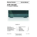
AVR 165/230
5.1 CHANNEL A/V RECEIVER
Released EU2011
Harman Consumer Group, Inc.
Rev 0, 10/2011
8500 Balboa Boulevard
Northridge, California 91329
CONTENTS
EXPLODED VIEW AND PARTS
15
PARTS LIST
16
IC PINOUTS
40
PCB DRAWINGS
87
BLOCK DIAGRAMS
97
WIRING DIAGRAM
99
AMP BIAS ADJUSTMENT
100
SCHEMATIC DIAGRAMS
101-111
ESD WARNING
2
FRONT AND REAR PANELS
3
REMOTE CONTROL
7
RESET REMOTE AND PROCESSOR
9
TROUBLESHOOTING GUIDE
10
BASIC SPECIFICATIONS
11
PACKAGE LISTS AND PARTS
13
DISASSEMBLY
14
Each precaution in this manual should be followed during servicing.
Components identified with the IEC symbol
in the parts list are special significance to safety. When replacing a component identified with
, use only the replacement parts designated, or parts with the same ratings or resistance, wattage, or voltage that are designated in the
parts list in this manual. Leakage-current or resistance measurements must be made to determine that exposed parts are acceptably
insulated from the supply circuit before retuming the product to the customer.
Some semiconductor (solid state) devices can be damaged easily by static electricity. Such components commonly are called
Electrostatically Sensitive (ES) Devices. Examples of typical ES devices are integrated circuits and some field effect transistors and
semiconductor "chip" components.
The following techniques should be used to help reduce the incidence of component damage caused by static electricity.
1. Immediately before handling any semiconductor component or semiconductor-equipped assembly, drain off any electrostatic charge on
your body by touching a known earth ground. Alternatively, obtain and wear a commercially available discharging wrist strap device,
which should be removed for potential shock reasons prior to applying power to the unit under test.
2. After removing an electrical assembly equipped with ES devices, place the assembly on a conductive surface such as aluminum foil, to
prevent electrostatic charge build-up or exposure of the assembly.
3. Use only a grounded-tip soldering iron to solder or unsolder ES devices.
4. Use only an anti-static solder removal device. Some solder removal devices not classified as "anti-static" can generate electrical charges
sufficient to damage ES devices.
5. Do not use freon-propelled chemicals. These can generate electrical change sufficient to damage ES devices.
6. Do not remove a replacement ES device from its protective package until immediately before you are ready to install it. (Most replacement
ES devices are packaged with leads electrically shorted together by conductive foam, aluminum foil or comparable conductive material.)
7. Immediately before removing the protective material from the leads of a replacement ES device, touch the protective material to the
chassis or circuit assembly into which the device will be installed.
Be sure no power is applied to the chassis or circuit, and observe all other safety precautions.
8. Minimize bodily motions when handling unpackaged replacement ES devices. (Otherwise harmless motion such as the brushing together
or your clothes fabric or the lifting of your foot from a carpeted floor can generate static electricity sufficient to damage an ES devices.
CAUTION :
Harman Kardon
AVR 165/230V Service Manual
Page 2 of 111
4
AVR 1650/AVR 165
Front-Panel Controls
Front-Panel Controls
power
Indicator
Message
display
Volume
knob
Surround Mode
Select buttons
Set
button
Ir
Sensor
power
button
left/right
buttons
headphone Jack/
ezSet/eq Mic
connector
Source Select
buttons
tuning Mode
button
digital Input
button
Surround-Mode
category button
up/down buttons/
tuning buttons
uSb
port
Aux Analog
Audio Input
connector
channel
level control
button
Harman Kardon
AVR 165/230V Service Manual
Page 3 of 111
5
AVR 1650/AVR 165
ENGL
IS
H
Front-Panel Controls, continued
Front-Panel Controls, continued
Power indicator: this led has three possible modes:
led is off: Indicates that the AVr is unplugged or the rear-panel Main power switch
•
is off.
led glows amber: Indicates that the AVr is in the Standby mode.
led glows amber: Indicates that the AVr is in the Standby mode.
•
led glows white: Indicates that the AVr is turned on.
•
IMPORTANT NOTE: If the protect message ever appears on the AVr’s front-panel
Message display, turn off the AVr and unplug it from the Ac outlet. check all speaker
wires for a possible short circuit (the “+” and “–” conductors touching each other
or both touching the same piece of metal). If a short circuit is not found, bring the
unit to an authorized harman kardon service center for inspection and repair before
using it again.
IR sensor: this sensor receives infrared (Ir) commands from the remote control. It is
important to ensure that the sensor is not blocked.
Set button: press this button to select the currently highlighted menu item.
Message display: Various messages appear in this two-line display in response to
Set button: press this button to select the currently highlighted menu item.
Message display: Various messages appear in this two-line display in response to
commands and changes in the incoming signal. In normal operation, the current source
name appears on the upper line, while the surround mode is displayed on the lower line.
when the on-screen display menu system (oSd) is in use, the current menu settings
appear.
Surround-Mode Select buttons: After you have selected the desired surround-mode
Surround-Mode Select buttons: After you have selected the desired surround-mode
category, press these buttons to select a specific mode within the category, such as to
change from dolby
®
pro logic
®
II Movie mode to logic 7
®
Movie mode. Surround-mode
availability depends on the nature of the source input signal, i.e., digital versus analog,
and the number of channels encoded within the signal.
Volume knob: turn this knob to raise or lower the volume.
Volume knob: turn this knob to raise or lower the volume.
Power button: press this button to turn the AVr on or to place it in the Standby mode.
Tuning Mode button: this button toggles between manual (one frequency step at a
Tuning Mode button: this button toggles between manual (one frequency step at a
time) and automatic (seeks frequencies with acceptable signal strength) tuning mode. It
also toggles between stereo and mono modes when an FM station is tuned in.
Channel Level Control button: press this button to activate the channel-level adjustment
Channel Level Control button: press this button to activate the channel-level adjustment
feature. After pressing this button, use the up/down buttons to select the channel for
adjustment and use the left/right buttons to adjust the channel’s level.
Digital Input button: press this button to change the audio input for the current source.
Digital Input button: press this button to change the audio input for the current source.
use the left/right buttons to cycle through the available inputs. Although you can
assign any digital audio input to any source, the analog audio inputs are all permanently
dedicated to the source with which they are labeled.
Left/Right buttons: use these buttons to navigate the AVr’s menus.
Up/Down buttons/Tuning buttons: use these buttons to navigate the AVr’s menus.
Left/Right buttons: use these buttons to navigate the AVr’s menus.
Up/Down buttons/Tuning buttons: use these buttons to navigate the AVr’s menus.
when the radio is the active source, use these buttons to tune stations according to the
setting of the tuning Mode button (see above).
Surround-Mode Category button: press this button to select a surround-sound
Surround-Mode Category button: press this button to select a surround-sound
category. each press changes the surround-mode category: Auto Select, Virtual, Stereo,
Movie, Music and Video game. to change the specific surround-sound mode within the
category, use the Surround Mode Select buttons. See
Audio processing and Surround
Sound, on page 20, for more information on surround modes.
Headphone jack/EzSet/EQ Mic connector: connect a 1/4" stereo headphone plug to
Headphone jack/EzSet/EQ Mic connector: connect a 1/4" stereo headphone plug to
this jack for private listening. this jack is also used to connect the supplied microphone
for the ezSet/eq procedure described in
configure the AVr for Your Speakers, on
page 17.
Source Select buttons: press these buttons to select the active source.
USB port: You can use this port to perform software upgrades that may be offered in
Source Select buttons: press these buttons to select the active source.
USB port: You can use this port to perform software upgrades that may be offered in
the future. do not connect a storage device, a peripheral product or a pc here, unless
instructed to do so as part of an upgrade procedure.
Aux Analog Audio Input connector: connect an auxiliary source component that will
Aux Analog Audio Input connector: connect an auxiliary source component that will
be used only temporarily, such as a camcorder, portable music player or game console,
here.
Harman Kardon
AVR 165/230V Service Manual
Page 4 of 111

