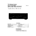
Harman Kardon AVR 100 (serv.man9) Service Manual ▷ View online
35 TECHNICAL SPECIFICATIONS
Technical Specifications
Audio Section
Stereo Mode
Continuous Average Power (FTC)
Stereo Mode
Continuous Average Power (FTC)
45 Watts per channel, 20Hz–20kHz,
@ < 0.07% THD, both channels driven into 8 ohms
@ < 0.07% THD, both channels driven into 8 ohms
Five-Channel Surround Modes
Power Per Individual Channel
Power Per Individual Channel
Front L&R channels:
40 Watts per channel,
@ < 0.07% THD, 20Hz–20kHz into 8 ohms
40 Watts per channel,
@ < 0.07% THD, 20Hz–20kHz into 8 ohms
Center channel:
40 Watts, @ < 0.07% THD, 20Hz–20kHz into 8 ohms
40 Watts, @ < 0.07% THD, 20Hz–20kHz into 8 ohms
Surround channels:
40 Watts per channel,
@ < 0.07% THD, 20Hz–20kHz into 8 ohms
40 Watts per channel,
@ < 0.07% THD, 20Hz–20kHz into 8 ohms
Input Sensitivity/Impedance
Linear (High Level)
200mV/47k ohms
Signal-to-Noise Ratio (IHF-A)
95dB
Surround System Adjacent Channel Separation
Analog Decoding
40dB
(Pro Logic, etc.)
Dolby Digital (AC-3)
Dolby Digital (AC-3)
55dB
DTS
55dB
Frequency Response
@ 1W (+0dB, –3dB)
10Hz–100kHz
High Instantaneous
Current Capability (HCC)
Current Capability (HCC)
±35 Amps
Transient Intermodulation
Distortion (TIM)
Distortion (TIM)
Unmeasurable
Rise Time
16 µsec
Slew Rate
40V/µsec
FM Tuner Section
Frequency Range
87.5–108MHz
Usable Sensitivity
IHF 1.3 µV/13.2dBf
Signal-to-Noise Ratio
Mono/Stereo 70/68dB
Distortion
Mono/Stereo 0.3/0.3%
Stereo Separation
40dB @ 1kHz
Selectivity
±400kHz, 65dB
Image Rejection
80dB
IF Rejection
90dB
Tuner Output Level
1kHz, ±75kHz Dev 500mV
AM Tuner Section
Frequency Range
520–1710kHz
Signal-to-Noise Ratio
45dB
Usable Sensitivity
Loop 500µV
Distortion
1kHz, 50% Mod 0.8%
Selectivity
±10kHz, 30dB
Video Section
Video Format
NTSC
Input Level/Impedance
1Vp-p/75 ohms
Output Level/Impedance 1Vp-p/75 ohms
Video Frequency
Video Frequency
10Hz–8MHz (–3dB)
Response
General
Power Requirement
AC 120V/60Hz
Power Consumption
72W idle, 694W maximum
(2 channels driven)
(2 channels driven)
Dimensions (Max)
Width
17.3 inches (440mm)
Height
6.5 inches (165mm)
Depth
17.1 inches (435mm)
Weight
31 lb (15.4 kg)
Depth measurement includes knobs, buttons and terminal connections.
Height measurement includes feet and chassis.
All features and specifications are subject to change without notice.
Height measurement includes feet and chassis.
All features and specifications are subject to change without notice.
Harman Kardon is a registered trademark, and Power for the Digital Revolution is a
trademark, of Harman Kardon, Inc.
trademark, of Harman Kardon, Inc.
*Manufactured under license from Dolby Laboratories.
“Dolby,” “Pro Logic,” “AC-3” and the Double-D symbol are
trademarks of Dolby Laboratories. Confidential Unpublished
Works. ©1992–1999 Dolby Laboratories, Inc. All rights reserved.
“Dolby,” “Pro Logic,” “AC-3” and the Double-D symbol are
trademarks of Dolby Laboratories. Confidential Unpublished
Works. ©1992–1999 Dolby Laboratories, Inc. All rights reserved.
†DTS and DTS Surround are trademarks of Digital Theater Systems, Inc.
††UltraStereo is a trademark of UltraStereo Corp.
2
ELECTROSTATICALLY SENSITIVE (ES) DEVICES
AVR100 / AVR200
Some semiconductor (solid state) devices can be damaged easily by static electricity. Such components commonly
are called Electrostatically Sensitive (ES) Devices. Examples of typical ES devices are integrated circuits and some
field effect transistors and semiconductor “chip” components. The following techniques should be used to help
reduce the incidence of component damage caused by static electricity.
are called Electrostatically Sensitive (ES) Devices. Examples of typical ES devices are integrated circuits and some
field effect transistors and semiconductor “chip” components. The following techniques should be used to help
reduce the incidence of component damage caused by static electricity.
1. Immediately before handling any semiconductor component or semiconductor-equipped assembly, drain off any
electrostatic charge on your body by touching a known earth ground. Alternatively obtain and wear a commercially
available discharging wrist strap device, which should be removed for potential shock reasons prior to applying
power to the unit under test.
electrostatic charge on your body by touching a known earth ground. Alternatively obtain and wear a commercially
available discharging wrist strap device, which should be removed for potential shock reasons prior to applying
power to the unit under test.
2. After removing an electrical assembly equipped with ES devices, place the assembly on a conductive surface
such as aluminum foil, to prevent electrostatic charge buildup or exposure of the assembly.
such as aluminum foil, to prevent electrostatic charge buildup or exposure of the assembly.
3. Use only a grounded-tip soldering iron to solder or unsolder ES devices.
4. Use only an anti-static solder removal device. Some solder removal devices not classified as “anti-static” can
generate electrical charges sufficient to damage ES devices,
generate electrical charges sufficient to damage ES devices,
5. Do not use freon-propelled chemicals. These can generate electrical change sufficient to damage ES devices.
6. Do not remove a replacement ES device from its protective package until immediately before you are ready to
install it. (Most replacement ES devices are packaged with leads electrically shorted together by conductive foam,
aluminum foil or comparable conductive material.)
install it. (Most replacement ES devices are packaged with leads electrically shorted together by conductive foam,
aluminum foil or comparable conductive material.)
7. Immediately before removing the protective material from the leads of a replacement ES device, touch the
protective material to the chassis or circuit assembly into which the device will be installed.
protective material to the chassis or circuit assembly into which the device will be installed.
CAUTION : Be sure no power is applied to the chassis or circuit, and observe all other safety precautions.
8. Minimize bodily motions when handling unpacked replacement ES devices. (Otherwise harmless motion such as
the brushing together or your clothes fabric or the lifting of your foot from a carpeted floor can generate static
electricity sufficient to damage an ES device.)
the brushing together or your clothes fabric or the lifting of your foot from a carpeted floor can generate static
electricity sufficient to damage an ES device.)
PRODUCT SAFETY NOTICE
Each precaution in this manual should be followed during servicing.
Components identified with the IEC symbol
Components identified with the IEC symbol
the parts list are of special significance to safety. When
replacing a component identified with , use only the replacement parts designated, or parts with the
same ratings or resistance, wattage or voltage that are designated in the parts list in this manual.
Leakage-current or resistance measurements must be made to determine that exposed parts are acceptably
insulated from the supply circuit before returning the product to the customer.
same ratings or resistance, wattage or voltage that are designated in the parts list in this manual.
Leakage-current or resistance measurements must be made to determine that exposed parts are acceptably
insulated from the supply circuit before returning the product to the customer.
3

