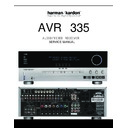
Harman Kardon AVR 335 (serv.man2) Service Manual ▷ View online
S5
S1
S2
6.2dB
Amp
75
dirver
6.2dB
Amp
6.2dB
Amp
S4
S3
S6
S7
20K
20K
20K
13
Vin1
V+
V-
SW2
SW1
Vout1
Vout2
Vout3
SW4
BLOCK DIAGAM (NJM2296M ) : IC41, 42, 43
SW3
GND
SW5
Vin2
Vin3
Vin4
Vin5
1
15
11
16
10
14
12
2
9
7
5
4
6
8
3
20K
20K
20K
20K
20K
75
dirver
75
dirver
NJM2068M (OP-AMP)
U-COM IC PIN ASSIGNMENT & DESCRIPTIONS
■
PIN
ASSIGNMENT (IC72)
(TOP VIEW)
(FPT-100P-M06)
1
P20/A16
P21/A17
P22/A18
P23/A19
P21/A17
P22/A18
P23/A19
P24/A20/PPG0
P25/A21/PPG1
P26/A22/PPG2
P27/A23/PPG3
P25/A21/PPG1
P26/A22/PPG2
P27/A23/PPG3
P30/A00/AIN0
P31/A01/BIN0
P31/A01/BIN0
V
SS
P32/A02/ZIN0
P33/A03/AIN1
P34/A04/BIN1
P34/A04/BIN1
P35/A05/ZIN1
P36/A06
P37/A07
P37/A07
P40/A08/SIN2
P41/A09/SOT2
P42/A10/SCK2
P42/A10/SCK2
P43/A11
P44/A12
P44/A12
V
CC
P45/A13
P46/A14/OUT4
P47/A15/OUT5
P47/A15/OUT5
P70/SIN0
P71/SOT0
P72/SCK0
P72/SCK0
P73/TIN0
2
3
4
5
6
7
8
9
3
4
5
6
7
8
9
10
11
12
13
14
15
16
17
18
19
20
21
22
23
24
25
26
27
28
29
30
11
12
13
14
15
16
17
18
19
20
21
22
23
24
25
26
27
28
29
30
X0A
X1A
P57/CLK
RST
P56/RDY
P55/HAK
P54/HRQ
P53/WRH
P52/WRL
P51/RD
P50/ALE
PA3/OUT3
PA2/OUT2
PA1/OUT1
PA0/OUT0
P97/IN1
P96/IN0
P95/PPG5
P94/PPG4
P93/FRCK/ADTG/CS3
P92/SCK1/CS2
P91/SOT1/CS1
P90/SIN1/CS0
P87/IRQ7
P86/IRQ6
P85/IRQ5
P84/IRQ4
P83/IRQ3
P82/IRQ2
MD2
X1A
P57/CLK
RST
P56/RDY
P55/HAK
P54/HRQ
P53/WRH
P52/WRL
P51/RD
P50/ALE
PA3/OUT3
PA2/OUT2
PA1/OUT1
PA0/OUT0
P97/IN1
P96/IN0
P95/PPG5
P94/PPG4
P93/FRCK/ADTG/CS3
P92/SCK1/CS2
P91/SOT1/CS1
P90/SIN1/CS0
P87/IRQ7
P86/IRQ6
P85/IRQ5
P84/IRQ4
P83/IRQ3
P82/IRQ2
MD2
80
79
78
77
76
75
74
73
72
71
70
69
68
67
66
65
64
63
62
61
60
59
58
57
56
55
54
53
52
51
79
78
77
76
75
74
73
72
71
70
69
68
67
66
65
64
63
62
61
60
59
58
57
56
55
54
53
52
51
31
P74/TOT0
P75
P76
P77
AV
CC
AVRH
AV
SS
P60/AN0
P61/AN1
P62/AN2
P63/AN3
Vss
P64/AN4
P65/AN5
P66/AN6
P67/AN7
P80/IRQ0
P81/IRQ1
MD0
MD1
32
33
34
35
36
37
38
39
40
41
42
43
44
45
46
47
48
49
50
P17/AD15/D15
P16/AD14/D14
P15/AD13/D13
P14/AD12/D12
P13/AD11/D11
P12/AD10/D10
P11/AD09/D09
P10/AD08/D08
P07/AD07/D07
P06/AD06/D06
P05/AD05/D05
P04/AD04/D04
P03/AD03/D03
P02/AD02/D02
P01/AD01/D01
P00/AD00/D00
V
CC
X1
X0
V
SS
100
99
98
97
96
95
94
93
92
91
90
89
88
87
86
85
84
83
82
81
MB9048
2
■
PIN DESCRIPTIONS
(IC72)
(Continued)
Pin No.
Pin name
Circuit
type
Function
LQFP*
1
QFP*
2
80
82
X0
A
Oscillator pin
81
83
X1
A
Oscillator pin
78
80
X0A
A
32 kHz oscillator pin
77
79
X1A
A
32 kHz oscillator pin
75
77
RST
B
Reset input pin
83 to 90 85 to 92
P00 to P07
C
(CMOS)
This is a general purpose I/O port. A setting in the pull-up
resistance setting register (RDR0) can be used to apply pull-up
resistance (RD00-RD07
resistance setting register (RDR0) can be used to apply pull-up
resistance (RD00-RD07
=
“1”) . (Disabled when pin is set for
output.)
AD00 to AD07
In multiplex mode, these pins function as the external address/
data bus low I/O pins.
data bus low I/O pins.
D00 to D07
In non-multiplex mode, these pins function as the external data
bus low output pins.
bus low output pins.
91 to 98
93 to
100
P10 to P17
C
(CMOS)
This is a general purpose I/O port. A setting in the pull-up
resistance setting resister (RDR1) can be used to apply pull-up
resistance (RD10-RD17
resistance setting resister (RDR1) can be used to apply pull-up
resistance (RD10-RD17
=
“1”) . (Disabled when pin is set for
output.)
AD08 to AD15
In multiplex mode, these pins function as the external address/
data bus high I/O pins.
data bus high I/O pins.
D08 to D15
In non-multiplex mode, these pins function as the external data
bus high output pins.
bus high output pins.
99,
100,
1,2
1 to 4
P20 to P23
E
(CMOS/H)
This is a general purpose I/O port. When the bits of external
address output control register (HACR) are set to "1" in external
bus mode, these pins function as general purpose I/O ports.
address output control register (HACR) are set to "1" in external
bus mode, these pins function as general purpose I/O ports.
A16 to A19
When the bits of external address output control register (HACR)
are set to "0" in multiplex mode, these pins function as address
high output pins (A16-A19).
are set to "0" in multiplex mode, these pins function as address
high output pins (A16-A19).
A16 to A19
When the bits of external address output control register (HACR)
are set to "0" in non-multiplex mode, these pins function as
address high output pins (A16-A19).
are set to "0" in non-multiplex mode, these pins function as
address high output pins (A16-A19).
3 to 6
5 to 8
P24 to P27
E
(CMOS/H)
This is a general purpose I/O port. When the bits of external
address output control register (HACR) are set to "1" in external
bus mode, these pins function as general purpose I/O ports.
address output control register (HACR) are set to "1" in external
bus mode, these pins function as general purpose I/O ports.
A20 to A23
When the bits of external address output control register (HACR)
are set to "0" in multiplex mode, these pins function as address
high output pins (A20-A23).
are set to "0" in multiplex mode, these pins function as address
high output pins (A20-A23).
A20 to A23
When the bits of external address output control register (HACR)
are set to "0" in non-multiplex mode, these pins function as
address high output pins (A20-A23).
are set to "0" in non-multiplex mode, these pins function as
address high output pins (A20-A23).
PPG0 to PPG3
PPG timer output pins.
Click on the first or last page to see other AVR 335 (serv.man2) service manuals if exist.

